Yaskawa VS-616G5 Series Revision F Programming Manual User Manual
Page 20
V/f
V/f w/PG Open Loop
Vector
Flux
Vector
20
VS-616G5 Programming Manual
Setting Range:
0.0 to 100.0s
Factory Default:
0.0s
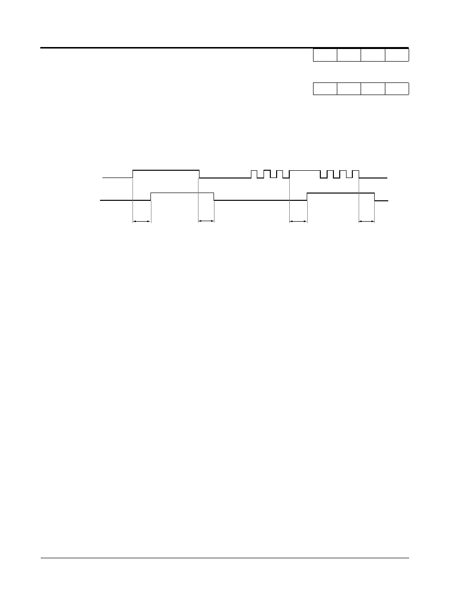
Sets the OFF-delay time in units of 0.1 second. The multi-function input must be “open” for longer
than the OFF-delay timer for the multi-function output to open.
B5
PID Control
The Proportional, Integral and Derivative (PID) control function provides closed-loop control and reg-
ulation of a system variable such as temperature or pressure. A control signal based on the difference
(or proportion) between a feedback signal and a desired setpoint is produced. Integration and deriva-
tive calculations are then performed on this signal, based upon the PID parameter settings (B5-01 to
B5-08), to minimize deviation, for more precise control.
Proportional - P
PID refers to the type of action used to control modulating equipment such as valves or dampers. With
proportional control, a control signal based on the difference between an actual condition and a
desired condition is produced. The difference, such as that between an actual temperature and setpoint
is the “error”. The inverter adjusts its output signal related directly to the error magnitude.
Integral - I
The integral action is designed to minimize offset. An integrating term is used to observe how long the
error condition has existed, summing the error over time. Once the system has stabilized, the offset
would be minimized.
Derivative - D
Overshoot refers to a control loop tendency to overcompensate for an error condition, causing a new
error in the opposite direction. Derivative action provides an anticipatory function that exerts a “brak-
ing” action on the control loop. When combined, the proportional integral, and derivative actions pro-
vide quick response to error, close adherence to the setpoint, and control stability.
B4-02 Off-delay Timer
Delay-OFF Timer
A
A
A
A
Multi-function Contact
Input: Timer Function
Multi-function Contact
Output: Timer Function
ON
ON
B4-01
Figure 8 Timing Diagram of Timer Function
B4-01
B4-02
ON ON ON
ON
ON ON ON
ON
B4-02
Section B: Application Parameters
B5 PID Control