4 dc connection – SMA WB 3000-21 Installation User Manual
Page 35
SMA Solar Technology AG
6 Electrical Connection
Installation Manual
WB3-5TL-21-IA-en-10
35
6.4 DC Connection
6.4.1 Connecting the Connection Cables to DC Connectors
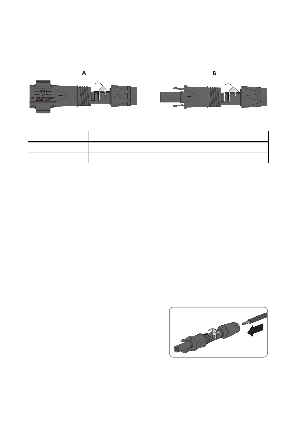
Figure 12: DC connectors
Required material (not included in the scope of delivery):
☐ 2 PV1-F cables for connecting the rectifier (maximum length: 30 m)
☐ 2 PV1-F cables for bridging the DC inputs on the inverter (length: 25 cm to 35 cm)
Cable requirements:
☐ External diameter: 5 mm to 8 mm
☐ Wire size: 2.5 mm² to 6 mm²
Assigning the PV1-F cables to the DC connectors:
• Connect one PV1-F cable for connecting the rectifier to a positive DC connector.
• Connect one PV1-F cable for connecting the rectifier to a negative DC connector.
• Connect each end of the PV1-F cable for bridging the DC inputs to a positive DC connector.
• Connect each end of the PV1-F cable for bridging the DC inputs to a negative DC connector.
Connect each connection cable to the appropriate DC connector according to the following
procedure.
1. Strip the insulation of the cable by 12 mm.
2. Lead the stripped cable all the way into the DC
connector. Ensure that the stripped cable and the
DC connector have the same polarity.
Position
Description
A
Negative DC connector
B
Positive DC connector
+