SMA WB 3000-21 Installation User Manual
Page 14
4 Product Description
SMA Solar Technology AG
14
WB3-5TL-21-IA-en-10
Installation Manual
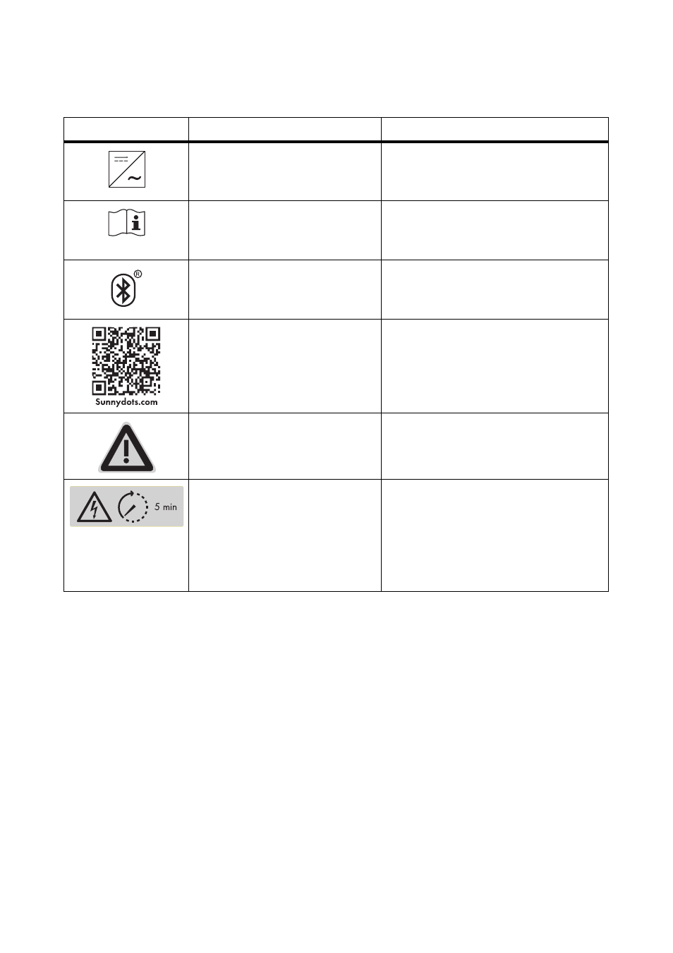
Symbols on the inverter
Symbol
Description
Explanation
Inverter
This symbol defines the function of the
green LED. The green LED indicates the
operating state of the inverter.
Observe documentation
This symbol defines the function of the
red LED. The red LED indicates an error.
Read this document to remedy the error.
Bluetooth
This symbol defines the function of the
blue LED. The blue LED indicates that the
Bluetooth communication is enabled.
QR Code
®
The QR Code
®
refers to the SMA bonus
program (for information on this, see
www.SMA-Bonus.com).
Danger
If a second protective conductor is
required, also ground the enclosure (see
Section 6.3.3).
Danger to life due to high
voltages in the inverter; observe
waiting time.
High voltages that can cause fatal
electric shocks are present in the live
components of the inverter. Disconnect
the inverter from any voltage sources
before performing any work on it
(see Section 9).