3 connecting the sunny island inverter – SMA SI 3.0-11 Quick Reference Guide V.3.0 User Manual
Page 32
5 Battery Backup Systems Without All-Pole Disconnection
SMA Solar Technology AG
32
Ersatzstrom-IS-en-30
Installation - Quick Reference Guide
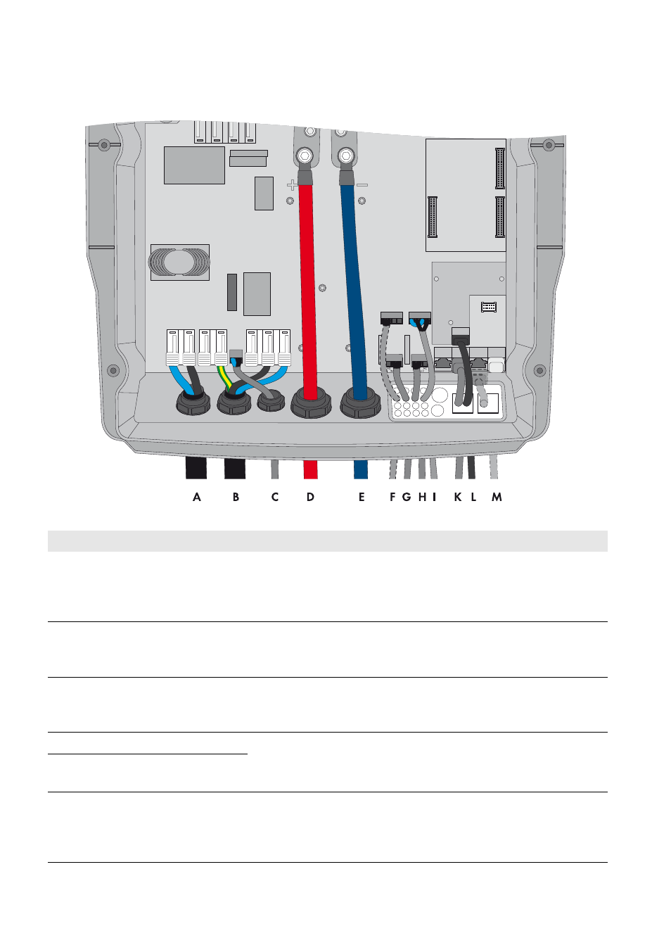
5.1.3 Connecting the Sunny Island Inverter
Figure 12: Connecting the Sunny Island inverter
Position Designation
Description/information
A
Cable for the control voltage Sunny Island: connection AC1 Loads/SunnyBoys terminals L and N
Automatic transfer switch: connection X5 terminals L and N
This cable is only required for phase coupling.
Conductor cross-section: 2.5 mm² to 16 mm²
B
AC power cable
Sunny Island: connection AC2 Gen/Grid terminals L, N
TT
,
and PE
Automatic transfer switch: connection X3 terminals L1, N, and PE
Conductor cross-section: 10 mm² to 16 mm²
C
Measuring cable for voltage
measurement
Sunny Island: connection ExtVtg terminals L and N
Automatic transfer switch: connection X4 terminals L1 and N
Conductor cross-section: 1.5 mm² to 2.5 mm²
D
DC+ cable
Battery connection
Conductor cross-section: 50 mm² to 95 mm²
Cable diameter: 14 mm to 25 mm
E
DC − cable
F
Measuring cable of the
battery temperature sensor
Sunny Island: BatTmp connection
You only have to connect a battery temperature sensor if lead-acid batteries
are used. Mount the battery temperature sensor in the middle of the battery
connection, in the upper third of the battery cell.