SMA SI 3.0-11 Quick Reference Guide V.3.0 User Manual
Page 14
3 Information and System Description
SMA Solar Technology AG
14
Ersatzstrom-IS-en-30
Installation - Quick Reference Guide
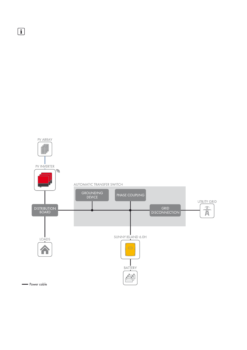
3.3 Design and Functions of the Battery Backup System
Figure 1: Block circuit diagram of a single-phase battery backup system
In the event of grid failure, a battery backup system with Sunny Island supplies loads with energy and a grid-tie PV system
with voltage. In the event of grid failure, an automatic transfer switch disconnects the battery backup grid from the utility
grid. After disconnection, the loads and the PV system have no supply for approximately five seconds, until the battery
backup system can provide active and reactive power once more. The battery backup system supplies the loads and the
PV system can synchronize with the battery backup grid and feed in.
Information on the PV system
Maximum PV system power
In battery backup systems, the maximum power of the PV system depends on the total power of the Sunny Island.
• Maximum output power of the PV system per SI3.0M-11: 4,600 W
• Maximum output power of the PV system per SI4.4M-11: 4,600 W
• Maximum output power of the PV system per SI6.0H-11: 9,200 W
• Maximum output power of the PV system per SI8.0H-11: 12,000 W
Observance of the maximum output power of the PV system is a requirement for stable operation of the battery
backup system during a grid failure.
Frequency-dependent control of active power feed-in
In battery backup systems, the active power of the PV inverters must be controllable depending on the frequency.
• With existing systems, ensure that the PV inverters are controllable depending on the frequency (see Planning
Guidelines "SMA Flexible Storage System with Battery Backup Function").