9 tilting the working plane (software option 1), Application, function – HEIDENHAIN TNC 620 (73498x-01) User Manual
Page 432
432
Manual operation and setup
13.9 Tilting the w
o
rk
ing plane (sof
tw
ar
e option 1)
13.9 Tilting the working plane
(software option 1)
Application, function
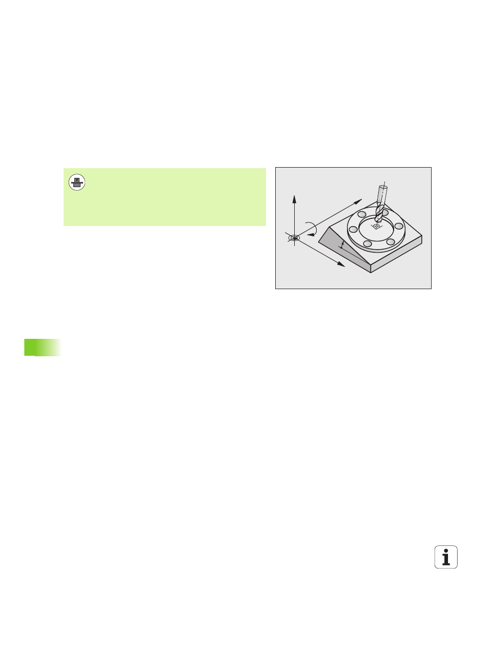
The TNC supports the tilting functions on machine tools with swivel
heads and/or tilting tables. Typical applications are, for example,
oblique holes or contours in an oblique plane. The working plane is
always tilted around the active datum. The program is written as usual
in a main plane, such as the X/Y plane, but is executed in a plane that
is tilted relative to the main plane.
There are three functions available for tilting the working plane:
Manual tilting with the 3-D ROT soft key in the Manual Operation
mode and El. Handwheel mode, see "Activating manual tilting", page
435
Tilting under program control, Cycle 19 WORKING PLANE in the part
program (see User’s Manual, Cycles, Cycle 19 WORKING PLANE)
Tilting under program control, PLANE function in the part program
(see "The PLANE function: Tilting the working plane (software
option 1)" on page 349)
The TNC functions for "tilting the working plane" are coordinate
transformations. The working plane is always perpendicular to the
direction of the tool axis.
X
Z
Y
B
10°
The functions for tilting the working plane are interfaced to
the TNC and the machine tool by the machine tool builder.
With some swivel heads and tilting tables, the machine
tool builder determines whether the entered angles are
interpreted as coordinates of the rotary axes or as angular
components of a tilted plane. Refer to your machine tool
manual.