Introduction – HEIDENHAIN TNC 620 (73498x-01) User Manual
Page 385
HEIDENHAIN TNC 620
385
1
1
.6 Thr
ee-dimensional t
o
ol compensation (sof
tw
ar
e option 2)
11.6 Three-dimensional tool
compensation (software
option 2)
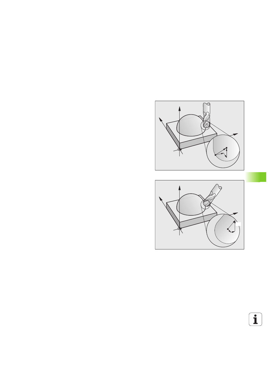
Introduction
The TNC can carry out a three-dimensional tool compensation (3-D
compensation) for straight-line blocks. Apart from the X, Y and Z
coordinates of the straight-line end point, these blocks must also
contain the components NX, NY and NZ of the surface-normal vector
(see "Definition of a normalized vector" on page 386).
If you want to carry out a tool orientation, these blocks need also a
normalized vector with the components TX, TY and TZ, which
determines the tool orientation (see "Definition of a normalized vector"
on page 386).
The straight-line end point, the components for the surface-normal
vector as well as those for the tool orientation must be calculated by
a CAM system.
Application possibilities
Use of tools with dimensions that do not correspond with the
dimensions calculated by the CAM system (3-D compensation
without definition of the tool orientation).
Face milling: compensation of the milling machine geometry in the
direction of the surface-normal vector (3-D compensation with and
without definition of the tool orientation). Cutting is usually with the
end face of the tool.
Peripheral milling: compensation of the mill radius perpendicular to
the direction of movement and perpendicular to the tool direction
(3-D radius compensation with definition of the tool orientation).
Cutting is usually with the lateral surface of the tool.
Z
Y
X
P
T
NZ
P
NX
NY
Z
Y
X
TX
TY
TZ