HEIDENHAIN ND 1300 CNC Setup User Manual
Page 45
36
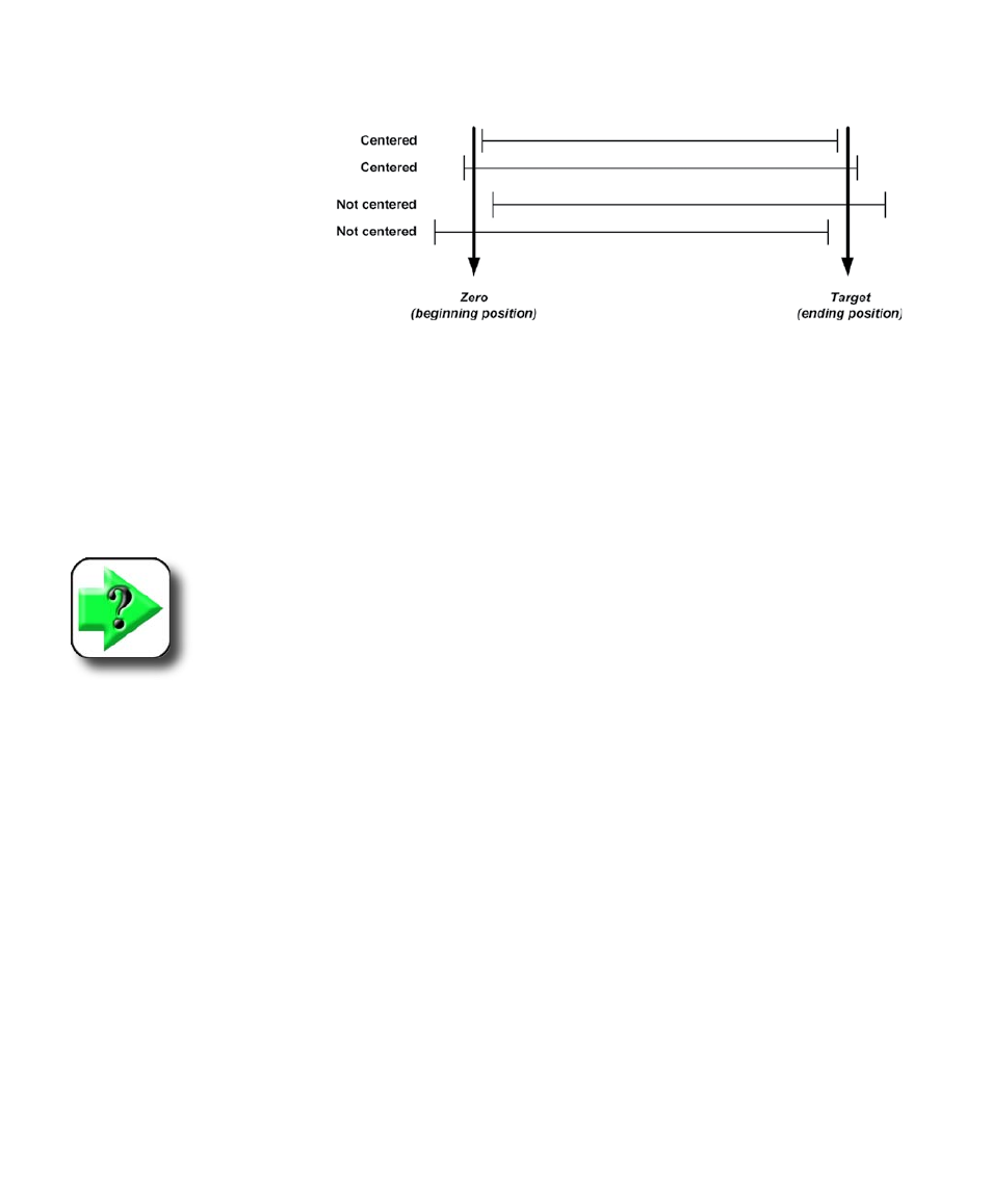
Axis end-positions centered?
When the axis end-positions
are centered, repeated CNC
axis tests will begin at or near
zero and end at or near the tar-
get position. This range of mo-
tion will be centered as shown
here.
Enter Current Voltage into Drift Offset field
Drift offset values are used to compensate for motor amplifier offset voltages in servo motor systems.
Changing the Drift offset value shifts the zero and target end-positions of the entire range of motion. Cen-
tering the range of motion can relax the requirement for large integral terms and results in more accurate
positioning. If the zero and target positions must be shifted to center the range of axis motion, begin by
entering value shown by the Current voltage field into the Drift offset field, then conduct more test moves
and increase or decrease the Drift offset value as necessary.
NOTE
Drift offset adjustments only apply to servo motor systems.
Axis end-positions accurate?
As an axis approaches its final target position, the following error drops to very small values. In some
servo systems the frictional forces opposing axis motion cannot be overcome by proportional gain alone
and the final axis position falls short of the target position. In these cases, some integral should be added
to servo systems to achieve acceptable end positioning. If end positioning is a problem in stepper systems,
increasing continuation debounce time can help.
User perception is a common reason for tuning systems to achieve levels of accuracy down to tenths or
hundredths of Microns. Perceived system goodness is often based on position accuracy that is achievable
but unnecessary for the applications they are intended to fill. The costs of ultra-high precision positioning
for systems with high frictional forces are increased complexity and the requirement for more frequent PID
loop retuning. Adding the integral term to PID loop control provides the additional gain for the small fol-
lowing errors required for precise positioning, but also has the potential to react with existing proportional
and derivative terms to produce axis instability and oscillation. In these cases, it is likely that the entire
tuning process will need to be repeated at least a few times until an acceptable balance of PID control
terms is found. Ultimately, the decision regarding the perceived or actual need for very high end-position
accuracy should be considered when applying integral.
CNC Setup and PID Loop Tuning Guide