Discussion of pid control parameters – HEIDENHAIN ND 1300 CNC Setup User Manual
Page 27
1
3
CNC Setup
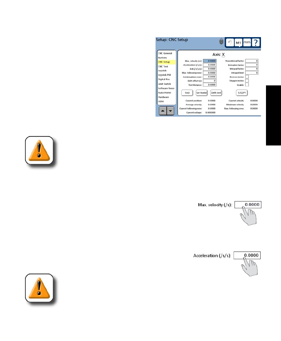
Discussion of PID control parameters
The motion and positioning performance of each axis
are determined by PID control terms and other axis setup
parameters contained in the CNC Setup screen.
PID control terms and other axis setup parameters are
identical for all axis screens. Since the screens are iden-
tical, only the X-axis screen in shown in these pages, but
the descriptions of PID control terms apply equally well
to all axis screens.
The brief description of the PID control terms provided
here. Additional detailed information regarding the in-
teractions and trade-offs between PID control parameters is included later in this chapter.
CAUTION
This discussion is only intended to familiarize you with control parameters used in
the PID loop tuning procedure provided later in this chapter. Refer to the PID loop
tuning procedure before entering setup data into the CNC Setup screen.
Max velocity
When the QC-320 performs CNC moves, vector velocities can be limited to prevent exceeding the maxi-
mum capability of the machine axis. Enter the desired maximum velocity value for an axis into the Max
velocity field to satisfy the specific hardware requirements and accommo-
date physical limitations of each system.
Acceleration
When the QC-320 performs CNC moves, vector accelerations can be limited to prevent exceeding the
maximum capability of the machine axis. Enter the desired acceleration value for an axis into the Ac-
celeration field to satisfy the specific hardware requirements and accom-
modate physical limitations of each system.
CAUTION
Specifying axis velocities and accelerations that are close to or equal the capability of
the machine can cause excessive following errors that halt the machine and result in
premature wear.
Discussion of PID Control Parameters