Cnc setup and pid loop tuning guide – HEIDENHAIN ND 1300 CNC Setup User Manual
Page 26
1
NOTE
Once the final target position is reached, no further drive signals are applied to the mo-
tors of stepper systems. However, drive signals continue to be applied to the motors of
servo systems to hold the final position. This requirement for actively holding a stable
position in servo systems contributes to the increased complexity of tuning servo motor
systems.
CNC system performance depends on the mechanical, electrical and PID loop characteristics of each axis
of motion. The mechanical characteristics of the axes are usually different and include variables such as
mass, static and dynamic friction, motor torque, lead screw pitch, system inertia and mechanical backlash.
Electrical characteristics include variables such as amplifier gain, amplifier offset, tachometer gain and
encoder resolution. The PID loop characteristics of the axes are also usually different and depend on the
PID control terms specified during loop tuning.
PID loop performance should only satisfy the actual application requirements of the system. Well de-
signed systems are usually capable of exceeding the application requirements that they are intended to fill.
This additional performance margin should not be used unnecessarily. It is included by system designers
to insure system stability and as a resource to be used in the future as the equipment or environmental
conditions change and the system must be retuned to remain in compliance. Systems that are tuned to
provide unnecessarily high levels of performance tend to be less stable, more difficult to tune and require
retuning more often.
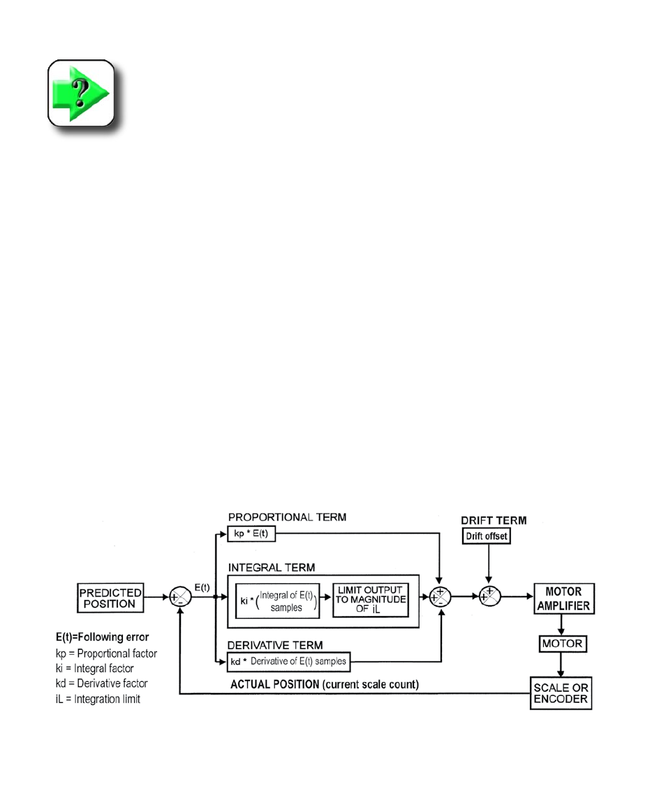
A detailed diagram of the simplified PID loop shown earlier is presented below. This diagram shows the
individual PID control terms of the loop. Descriptions of the individual control terms and more detailed
discussions of trade-offs between performance and application requirements are included in subsequent
pages.
Detailed PID control loop diagram
CNC Setup and PID Loop Tuning Guide