HEIDENHAIN ND 1300 CNC Setup User Manual
Page 13
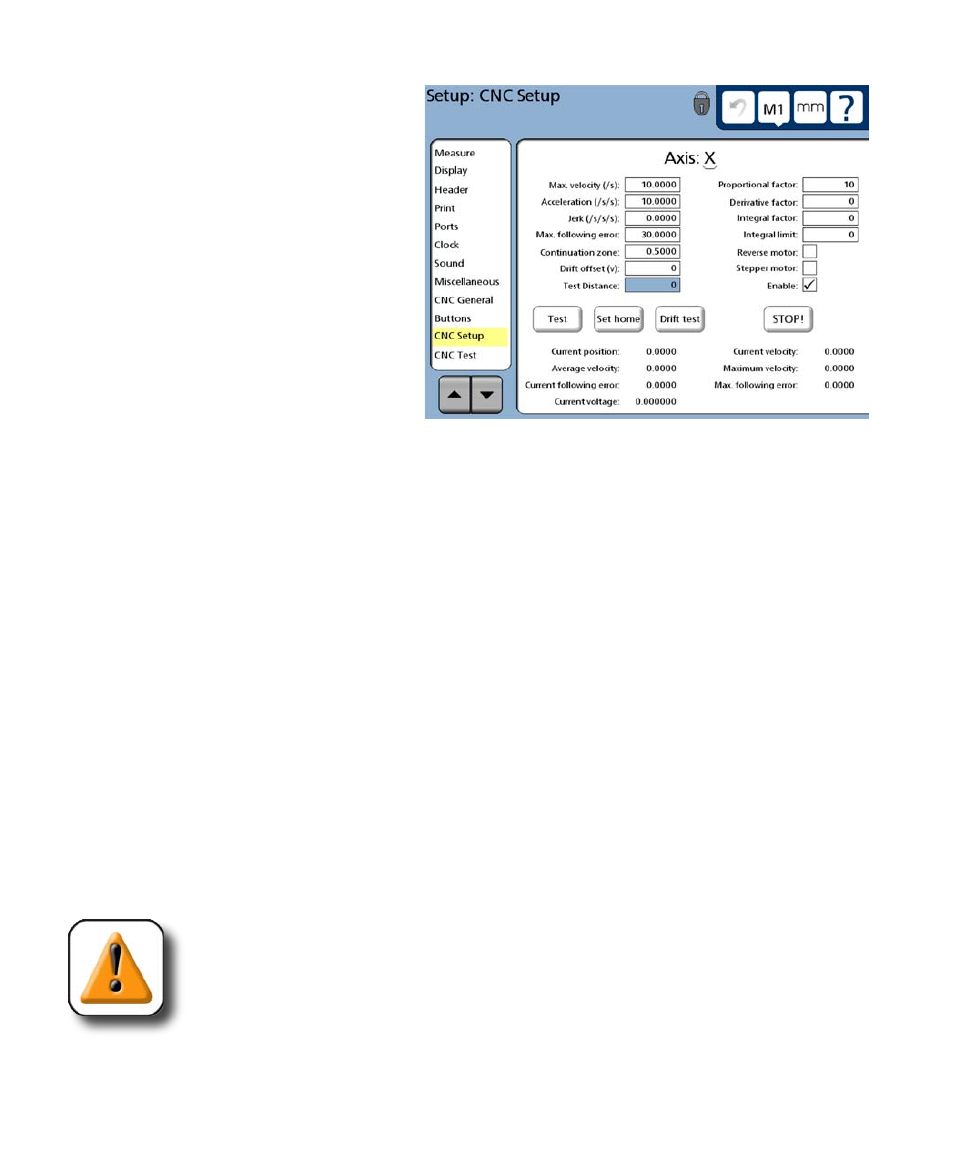
CNC Setup and PID Loop Tuning Guide
5 Enter the following initial values into
the X-axis data fields:
• Max velocity = 10
• Acceleration = 10
• Jerk = 0
• Max following error = 30
• Continuation zone = 0.5
• Drift offset = 0
• Proportional factor
For servo system = 20
For stepper system = 5
• Derivative factor = 0
• Integral factor = 0
• Integral limit = 0
• Reverse motor = box empty
• Stepper motor = box checked only if a stepper motor is used on this axis
• Enable = box checked
• Test distance = 10
The remainder of this procedure will initiate tests that move the axis a 10 mm test distance. During these
CNC moves, the Current position value will be observed at the bottom of the CNC Setup screen. It is
unlikely that any significant axis motion will occur until the motor amplifier gain (Proportional factor) is
increased, so the procedure usually becomes an iteration of touching the Test button, observing the Cur-
rent position value
, increasing the Proportional factor and touching the Test button again until definite
axis motion is observed.
When the axis moves in response to the test, the following determination of motor direction can be made:
• The motor is not reversed when the Current position value moves to or near the 10 mm target
position and stops.
• The motor is reversed when the Current position value continues beyond or away from
the 10 mm target at increasing velocities.
CAUTION
Reversed axes can move very quickly. If an axis begins to run away, touch the Stop
button
immediately.
The Stop button is not intended as a substitute for hard-contact emergency stop
switches. While touching the Stop button is a convenient way to halt axis motion, do not rely com-
pletely on this software interface - always be prepared to use the emergency stop button to halt
motion.