Description of switching output functions – HEIDENHAIN ND 760 E User Manual
Page 20
20
Description of Switching Output Functions
(Settings in parameter P21: STANDARD)
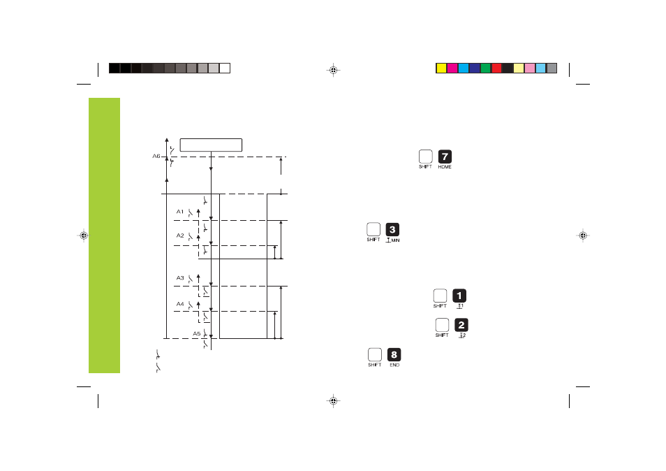
After an EDM process, the transistors A1, A2, A3, A4 and A6
are locked. A5 is conductive.
Description
of
S
witching
Output
Functions
START
Workpiece surface = 0
All
transistors
conductive
The
transistors
A
1,
A
2,
A
3
and
A4
are
locked,
A
5
and
A6
are
conductive.
= transistor conductive
= transistor locked
A1, A2, A5, A6 switch whenever the the trigger point is
traversed.
A3, A4 switch only once, i.e. when the trigger point is
traversed for the first time.
Start position (HOME) referenced to display value 0,
programmable with the
keys.
Trigger points before MIN position
1st trigger point before MIN position, programmable with
the
keys.
2nd trigger point before MIN position, programmable in
parameter 17 which is protected by a code number.
Trigger points with respect to erosion depth
1st trigger point before reaching the erosion depth,
programmable with the keys.
2nd trigger point before reaching the erosion depth,
programmable with the keys.
Trigger point for erosion depth, programmable with the
keys.
Bateil1.pm6
21.01.2002, 09:39
20