Gpi i/o connector pinouts, User manual(sp2) ― workstation mode – Grass Valley T2 Classic iDDR Workstation Mode SP2 User Manual
Page 112
T2
―
User Manual(SP2) ― Workstation mode ―
112
Section 4 ―
APPENDIX
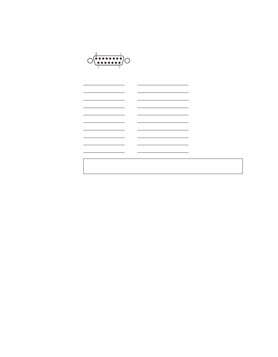
GPI I/O connector pinouts
8
1
15
9
Pin
Signal
Pin
Signal
1
Output 1
9
Input 1
2
Output 2
10
Input 2
3
Output 3
11
Input 3
4
Output 4
12
Input 4
5
Output 5
13
Input 5
6
Output 6
14
Input 6
7
NC
15
NC
8
Common Ground
SHELL
Common Ground
Note
T2 iDDR software supports outputs 1-6 and inputs 1-6 only. Pin 7 and Pin 15
are not used.
This manual is related to the following products: