Kayenne xl cabling, Me and local aux stripe connections, Touch screen menu panels (used with pcu) – Grass Valley Kayenne XL Package Installation v.7.0.4 User Manual
Page 83: Sections
Kayenne XL Package — Installation and Service Manual
83
Kayenne XL Cabling
Kayenne XL Cabling
Connectors on the outside bottom of the Control Panel tray connect to
numbered ports on the PCU, using special multi-pin cables that carry both
power and communications signals. Special cables are also used to connect
the Menu Panels to the PCU.
CAUTION Do not connect or disconnect the multi-pin cables linking a Kayenne XL
Control Panel tray or Menu Panel to the PCU while the PCU is powered up.
Damage to the Kayenne XL equipment can result.
ME and Local Aux Stripe Connections
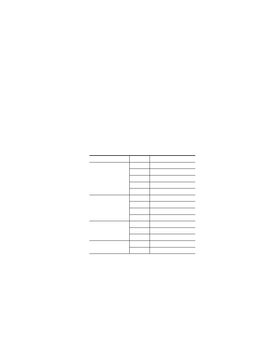
It is recommended that the PCU numbered ports be connected to Control
Panel Stripes in ascending ME order, followed by the Local Aux Stripe.
PCU port connections can be re-mapped, but this order matches the default
configuration. The table below shows the connections for various Kayenne
Control Panel models used in one workplace.
Touch Screen Menu Panels (Used with PCU)
Connect a single or primary Menu Panel to the PUC
Menu 1
connector, using
the supplied custom multi-pin cable. Connect an optional second Menu
Panel to the
Menu 2
connector. Menu Panels are assigned to suites during
Kayenne system configuration.
Table 12. PCU Port to Control Panel Stripe Connections
Control Panel Model
PCU Port
Panel Stripe
4-ME with Local Aux
1
ME 1 (top ME)
2
ME 2 (second ME)
3
ME 3 (third ME)
4
ME 4 (bottom ME)
5
Local Aux Stripe
3-ME with Local Aux
1
ME 1 (top ME)
2
ME 2 (second ME)
3
ME 3 (bottom ME)
4
Local Aux Stripe
2-ME with Local Aux
1
ME 1 (top ME)
2
ME 2 (bottom ME)
3
Local Aux Stripe
1-ME (no Local Aux)
2
Master EMEM, MFM (top tray)
1
ME (bottom tray)