Gpi circuits – Grass Valley Kaleido-X16 Installation v.7.70 User Manual
Page 29
17
Kaleido-X16
Hardware Description & Installation Manual
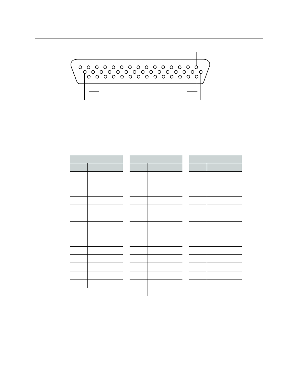
There are 44 GPI connector pins (40 not including GND) whose functions are as follows:
• 4 Ground (GND) pins
• 32 GPI Input pins
• 4 GPI Output Emitter pins (designated in the table, below, as “N”)
• 4 GPI Output Collector pins (designated in the table, below, as “P”)
The exact pinout for the GPI connector is as follows:
GPI Circuits
The individual GPI contacts are reconfigurable as either inputs or outputs. For interfacing
purposes, the input and output circuit configurations are as shown in the following
diagrams:
Bottom row
Middle row
Top row
Pin #
Description
Pin #
Description
Pin #
Description
31
GND
16
GPI Output N 1
1
GPI Output P 1
32
GPI Output N 2
17
GPI Output P 2
2
GPI Output N 3
33
GPI Output P 3
18
GPI Output N 4
3
GPI Output P 4
34
GPI Input 21
19
GPI Input 22
4
GPI Input 23
35
GND
20
GPI Input 24
5
GPI Input 25
36
GPI Input 26
21
GPI Input 27
6
GPI Input 28
37
GPI Input 29
22
GPI Input 30
7
GPI Input 31
38
GPI Input 20
23
GPI Input 32
8
GPI Input 18
39
GPI Input 16
24
GPI Input 19
9
GPI Input 15
40
GPI Input 14
25
GPI Input 17
10
GPI Input 12
41
GND
26
GPI Input 13
11
GPI Input 10
42
GPI Input 9
27
GPI Input 11
12
GPI Input 7
43
GPI Input 6
28
GPI Input 8
13
GPI Input 4
44
GPI Input 3
29
GPI Input 5
14
GPI Input 1
30
GPI Input 2
15
GND
Pin 15
Pin 1
Pin 30
Pin 44
Pin 31
Pin 16