Frame and electrical installation, Frame – Grass Valley Kaleido-X16 Installation v.7.70 User Manual
Page 17
5
Kaleido-X16
Hardware Description & Installation Manual
2 Insert the Kaleido-X16 frame at the designated location within the rack, and secure the
front of the frame to the rack by using suitable screws and washers (not included).
Frame and Electrical Installation
The Kaleido-X16 multiviewer is a self-contained unit consisting of a frame, redundant
power supplies, and various input and output cards. The monitor wall displays and external
control devices complete the system.
Frame
The Kaleido-X16 frame is 1 RU high. Input and output connectors are mounted on a
connector panel on the rear of the frame. The redundant power supply is installed in the
front of the frame. The front cover can be removed to give access to the PSUs,
CompactFlash card, USB connector, and basic LEDs.
The Kaleido-X16 frame incorporates the following key elements:
• A rack-mountable mechanical framework (for mounting into a 19-inch EIA rack)
• A removable door to cover and protect the front of the frame
• An optional redundant power supply
• Ventilation
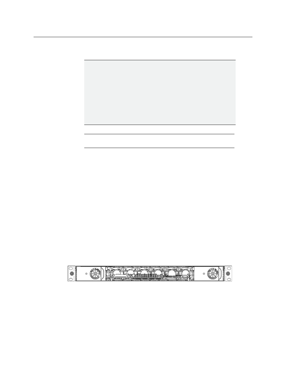
Front view of the Kaleido-X16 frame (PSUs installed; front cover removed)
IMPORTANT
Mobile Installation
If you are deploying your Kaleido-X16 in a mobile unit, it is your responsibility
to make sure the back of the multiviewer is securely attached to the rack. For
instance you may install a blank panel at the back of the rack, so that it meets
the top of the frame, to prevent the frame from bouncing away from the
support brackets.
Ventilation
For proper ventilation, make sure the front and side panel air vents are not
blocked and the air filter is clean.
Note:
The optional Kaleido-RCP2 may also be installed in a rack, by using
the KRCP-RK2 mounting kit.