Control, Linear time code (ltc), Gpi i/o – Grass Valley Kaleido-X16 Installation v.7.70 User Manual
Page 28
16
Kaleido-X16 Installation
Control
For more information about:
• SDTI audio specifications, see
• analog audio specifications, see
• AES output specifications, see
• triggering audio monitoring, see “Triggering Audio Monitoring” in the Operation of the
Monitor Wall chapter of the Kaleido-X User’s Manual.
• calibrating audio monitoring delay, see “Calibrating the Audio Monitoring Delay” in the
Calibrating the Kaleido-X chapter of the Kaleido-X User’s Manual.
• calibrating audio monitoring color, see “Calibrating the Audio Monitoring Color” in the
Calibrating the Kaleido-X chapter of the Kaleido-X User’s Manual.
Control
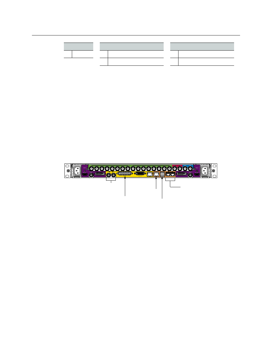
The connectors located in the middle of the rear connector panel (the yellow and orange
color-coded area) are Control connectors.
Linear Time Code (LTC)
The Kaleido-X16 supports two linear time code (LTC) inputs over BNC connectors. The
format is SMPTE ST 12 unbalanced (see
, on page 28 for specification
details).
GPI I/O
The Kaleido-X16 supports status monitoring, genlock and GPI interfacing. The rear
connector panel houses all input and output connectors associated with GPI I/O. The
Kaleido-X16 supports 32 GPI inputs and 4 GPI outputs. The GPI connector type is a DB-44
(female on the connector panel; male on the cable):
26 GND
17 PC In 1 Left (not supported)
8
PC In 1 Right (not supported)
18 NC
9
NC
Bottom row
Center row
Top row
BNC connectors
for LTC inputs
USB connectors (2)
RJ-45 connectors
(2) for RS-422
serial connections
RJ-45 Ethernet
connector
DB-44 connector
for GPI I/O