Compactflash, Signalling, Compactflash signalling – Grass Valley Kaleido-X16 Installation v.7.70 User Manual
Page 23
11
Kaleido-X16
Hardware Description & Installation Manual
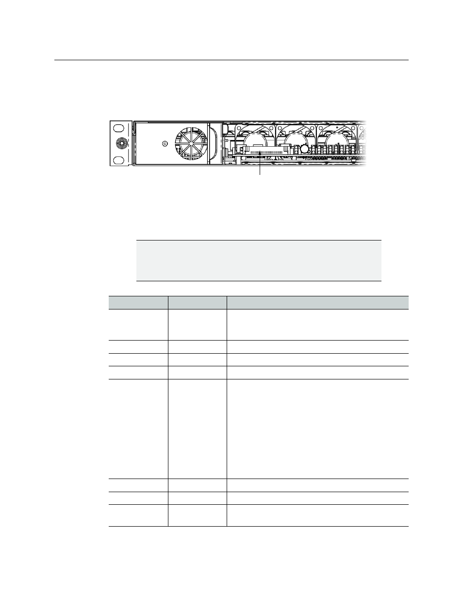
CompactFlash
In order to boot the CPU, you must ensure the appropriate CompactFlash (CF) card is
properly inserted in the CF slot (accessible from the front of the Kaleido-X16 frame). The CF
card contains the operating system required for a system boot.
For more information about starting the Kaleido-X16, see the Setting up the Kaleido-X16
chapter in the Kaleido-X16 Quick Start Guide.
Signalling
CF slot on front of Kaleido-X16 frame
IMPORTANT
The Kaleido-X16-D model supports two Heads while the Kaleido-X16-S
supports one Head. For details about the difference in connector support on
the two models, see
Connector label
Connector type
Function
DVI IN1-2
DVI
DVI input signal that can be used as a background in the
monitor wall display in place of the internally-generated
background.
INPUTS 1-16
BNC
HD/SD-SDI or composite video inputs 1 to 16.
MV OUT 1-2
HDMI
HDMI output including embedded audio for each head.
SDI OUT 1-2
BNC
Serial digital HD output signal for monitoring purposes.
REF
BNC
Reference signal to genlock the multiviewer to the local
plant. Supported Reference formats:
• SMPTE ST 170
• SMPTE ST 318
• ITU 624-4
• BUT 470-6
• PAL and NTSC composite sync
• SMPTE ST 274
• SMPTE ST 296
• SMPTE ST 240
LTC 1-2
BNC
Time code inputs.
GPI 1-44
DB-44 (female)
GPI input/output (unidirectional) connections.
RT OUT 1-2
BNC
Supports 3Gbps-SDI, HD-SDI, and SD-SDI router output
signals.