2 selecting monitoring signals – Grass Valley LDK 5417 User Manual
Page 20
LDK 5417 + LDK 4417 User’s Guide | Adapter controls
8
3.2
Selecting monitoring signals
Viewfinder display signal
The viewfinder can display local or external video signals. The viewfinder display signal
selection switch (8) determines the signal that is displayed in the viewfinder.
Set the first switch to LOC to display the local camera Y signal in the viewfinder. (The Ret.
button on the lens also selects this signal in parallel with this switch.) If set to the other
position, then the second switch determines the signal displayed in the viewfinder.
The second switch selects the signal displayed in the viewfinder when the viewfinder
signal selection switch is not in the LOC position. The signal then displayed is:
•
EXT 1
BS external input 1
•
EXT 2
BS external input 2.
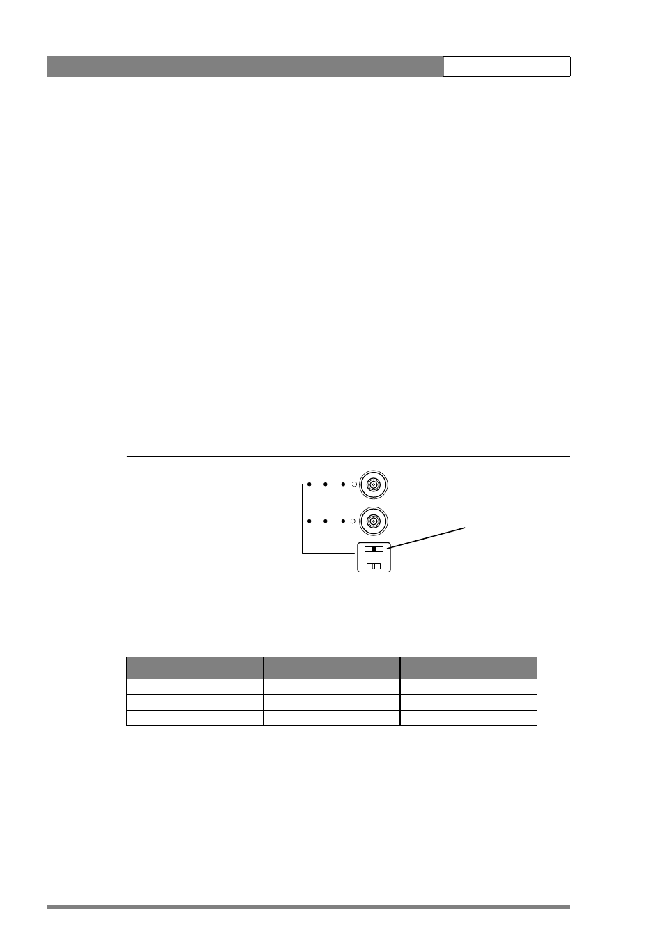
Video output signal selection
Two BNC connectors on the rear of the adapter carry viewfinder or external signals. To
select the output signal for these connectors use the top switch located underneath them
(the bottom switch is used for the audio microphone).
Figure 1-5. Video output switch and associated connectors
The video output signal selection switch shown above is a three-position switch which
determines the output video signal on the two video output connectors as shown in the
following table:
Switch position
VF/Ext1 connector
Ext1/Ext2 connector
Set to the right
External 1 signal
External 2 signal
Centered
Viewfinder signal
External 2 signal
Set to the left
Viewfinder signal
External 1 signal
Ext1 Ext2 Ext2
VF VF Ext1
Video output selection
switch