Connecting your cameraman cameras, Page 13 – Grass Valley CONTROL Center CameraMan Rev.B User Manual
Page 16
Install Your CONTROL Center
Page 13
Connecting Your CameraMan Cameras
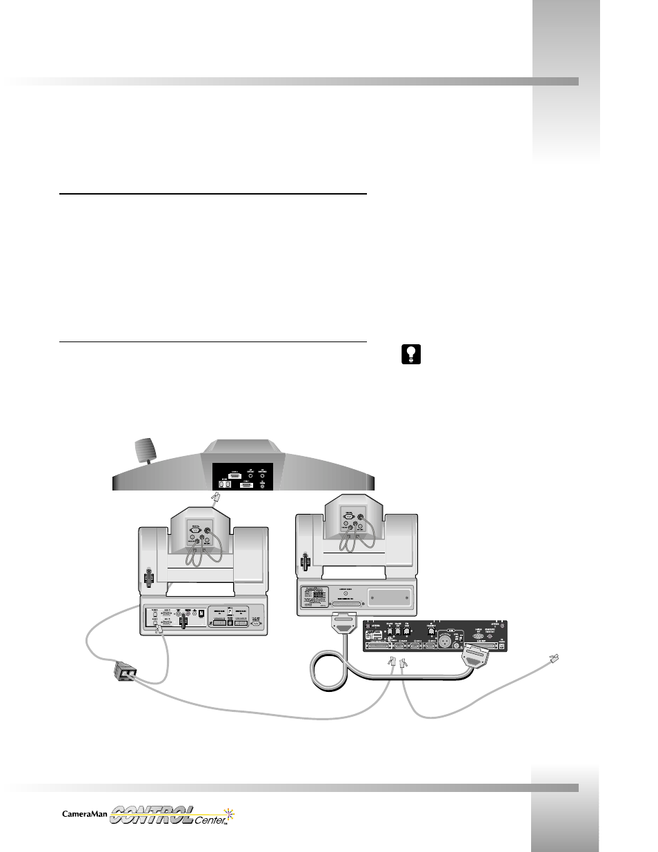
Camera Communications
The CONTROL Center communicates with CameraMan cameras through a CameraMan
Communication RS-485 cable connected to an RS-485 out port on the Control Unit. A single
camera is connected by plugging one end of the communication cable (each end has a modular
handset plug) into the RS-485 port on the Control Unit and plugging the other end into the
RS-485 port on the mini or main docking station of the camera. Multiple cameras are daisy-
chained together using additional communication cables and T-connectors if a camera has only
one RS-485 port or if the camera has two RS-485 ports, using additional cables and both ports.
Connecting to AC
The Power supply for the Control Unit and the AC cord for the Switcher were connected to
their units in the first installation steps. At this point, connect the AC plugs of the Control
Unit’s power supply and the Switcher’s power cord to AC outlets.
Do not power up until you have read the Power Up sequence in this manual.
After physically connecting all devices
and before Power Up, refer to page
23, the CameraMan and CONTROL
Center Setup section of this manual,
for information concerning camera
addresses and dip switch positions.
RS-485 from CONTROL
Center to T-Connector
T-Connector
RS-485 from T-Connector to
non-autoTRACK CameraMan
37-pin connector from
Main Docking Station to
autoTRACK equipped
CameraMan
RS-485 from T-Connector to
RS-485 IN port on Main
Docking Station
RS-485 from RS-485
OUT port on Main Docking
Station to up to 6 additional cameras
daisy-chained together