Configuration procedure – H3C Technologies H3C WX5500E Series Access Controllers User Manual
Page 41
33
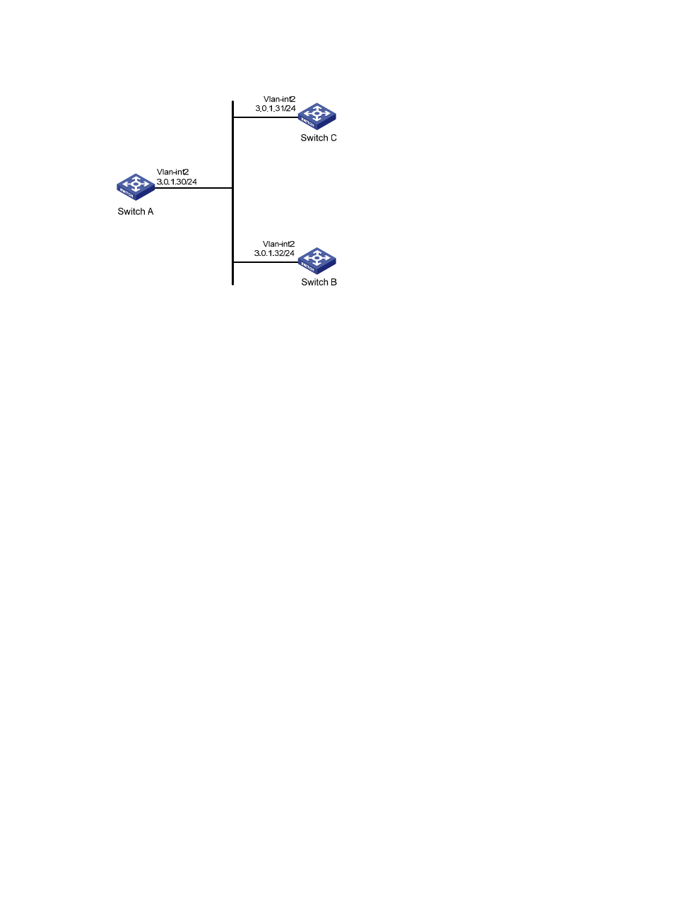
Figure 16 Network diagram
Configuration procedure
1.
Set the IP address for each interface as shown in
.
(Details not shown.)
2.
Configure Switch A:
# Configure Switch A to operate in NTP broadcast client mode and receive NTP broadcast
messages on VLAN-interface 2.
[SwitchA] interface vlan-interface 2
[SwitchA-Vlan-interface2] ntp-service broadcast-client
3.
Configure Switch B:
# Enable NTP authentication on Switch B. Configure an NTP authentication key, with the key ID of
88 and key value of 123456. Specify the key as a trusted key.
[SwitchB] ntp-service authentication enable
[SwitchB] ntp-service authentication-keyid 88 authentication-mode md5 123456
[SwitchB] ntp-service reliable authentication-keyid 88
# Configure Switch B to operate in broadcast client mode and receive NTP broadcast messages
on VLAN-interface 2.
[SwitchB] interface vlan-interface 2
[SwitchB-Vlan-interface2] ntp-service broadcast-client
4.
Configure Switch C:
# Configure Switch C to operate in NTP broadcast server mode and use VLAN-interface 2 to send
NTP broadcast packets.
[SwitchC] interface vlan-interface 2
[SwitchC-Vlan-interface2] ntp-service broadcast-server
[SwitchC-Vlan-interface2] quit
# Switch A synchronizes its local clock based on the received broadcast messages sent from
Switch C. Display NTP service status information on Switch A, and you can see that Switch A has
synchronized to Switch C, the stratum level of Switch A is 4, and the stratum level of Switch C is 3.
[SwitchA-Vlan-interface2] display ntp-service status
Clock status: synchronized
Clock stratum: 4