Figure b-5 – Verilink C100 (880-502893-001) Product Manual User Manual
Page 104
Sample Applications
B-10
Verilink C100 and C150 T1/FT1 CSU/DSU
6/15/99
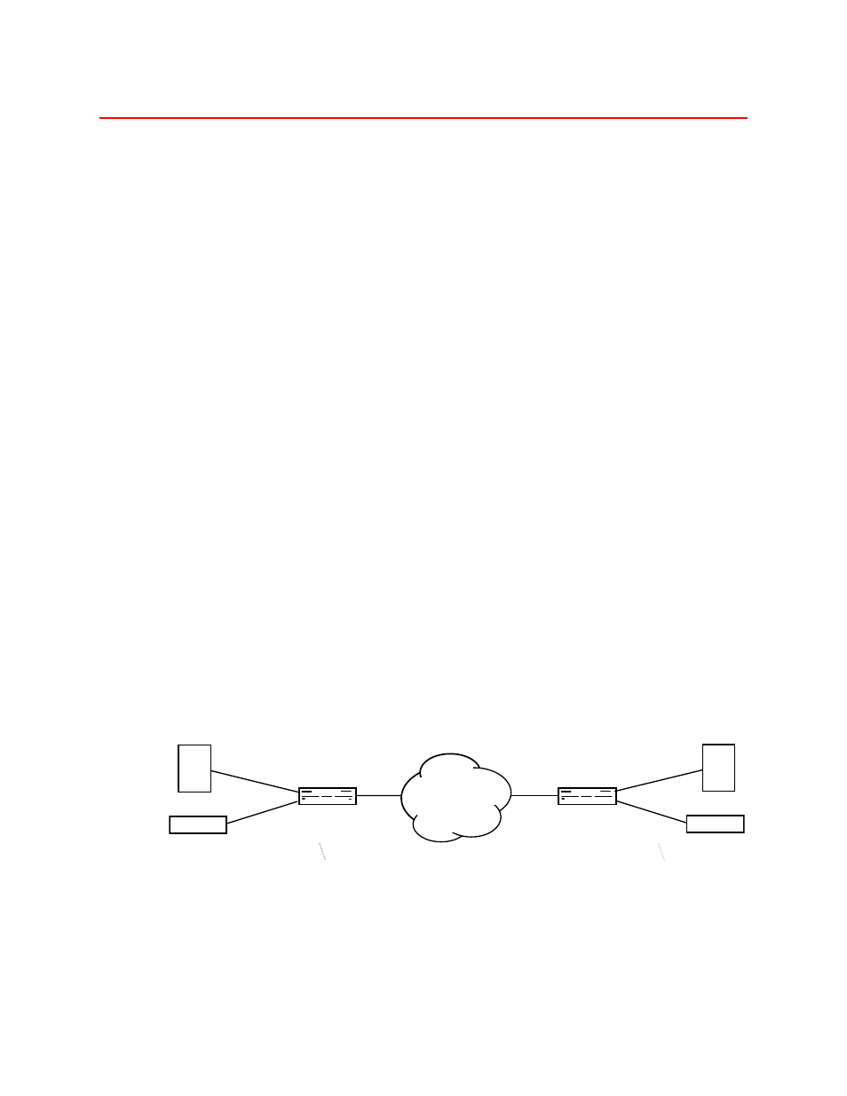
C150 T-1 CSU/DSU connecting two PBXs and two routers
shows a typical application with the CSU/DSU connecting
two sites and using both the Synchronous and DSX1 channels over a
T1 facility. The Network Interface (NI) side of each unit connects to the
T1 facility and the Customer Interface (CI) side of each unit connects to
the customer equipment. In this basic application, the user is using
224K bps (4 DS0’s times 56000 bps) with RS530 interfaces for the router
to router communications and the remaining 1280K bps (20 DS0’s
times 64000 bps) for PBX to PBX voice communications. The interface
on the local router is RS530, the interface on the remote router is V.35
and the PBXs support D4 framing with AMI encoding. The T-1 facility
is ESF with B8ZS encoding.
Table B-5 illustrates the switch configuration. Switch pack 3 positions 2
and 3 are On at both the local and remote sites because the PBXs are D4
framing with AMI framing. Switch pack 2 positions 1 and 2 are left in
the default position which is ESF framing with B8ZS encoding.
Timing is left in the default setting of Network provides timing with
Switch pack 2 positions 7 and 8 Off since the units are connected to a
carrier-provided T-1 Network.
Switch pack 4 positions 2 and 3 are both Off for RS530 interfaces.
Switch pack 5 positions 1,3, 5 and 7 are On (4 DS0’s times 56000 bps =
224000 bps). Care must be taken that the selected DS0’s are the same in
both units.
The Off position of the DIP switch is the rocker arm of the switch in its
lowest position (down) on the side of the switch closest to the front
panel.
Figure B-5
C150 CSU/DSUs connecting two PBXs and two routers over a T-1 facility
C150 only
Local Site
NI
CI DSX1
CI Sync
................
ROUTER
TEL-LINK
T1 CSU/DSU
NI
................
TEL-LINK
T1 CSU/DSU
PBX
CI DSX1
CI Sync
ROUTER
PBX
Remote Site
NETWORK
C150
C150