Mmi instrument physical addresses – Super Systems SuperDATA User Manual
Page 31
Super Systems Inc
Page 31 of 172
Super Data Operations Manual
setup.
ALM(PAL slot, Alarm offset, Alarm Bitmap Start Slot, Alarm ACK
Bitmap Slot, Number of Bitmap Slots).
e.g., ALM(36,0,0,0,0) for standard
Dualpro
e.g. ALM(36,400,60,64,4) for a Dualpro with Bitmapped alarm
support. Bitmapped alarm support is a custom feature in the Dualpro and is
implemented by some Dualpro programs. Normally this will be configured by
SSI personnel familiar with the DualPro programs. If you are not sure, do not
include Bitmapped support. Invalid configurations may cause spurious invalid
alarms to be reported on RealTime and in AlarmReports.
NOLOG
Optional. Applies to ALL instruments.
Do not log data from this channel.
Include this when communications are required for real-time data but are not
required for historical data logging. If this is not included, the channel will be
data logged at one minute intervals.
ABC
Optional. Applies to ALL instruments.
Alarm Block Configuration .
Caution:
any specified channel can use either ALM or ABC but not both.
Allows a custom
Alarm Block Bitmap (one word) to be setup for any instrument but generally
used only for non-programmable instruments that are not capable of
maintaining alarm bitmaps. See the section on Custom Alarm Block
Configuration.
TAG
Required. Applies to ALL instruments.
Instrument name. Limited to 12
Characters with no spaces.
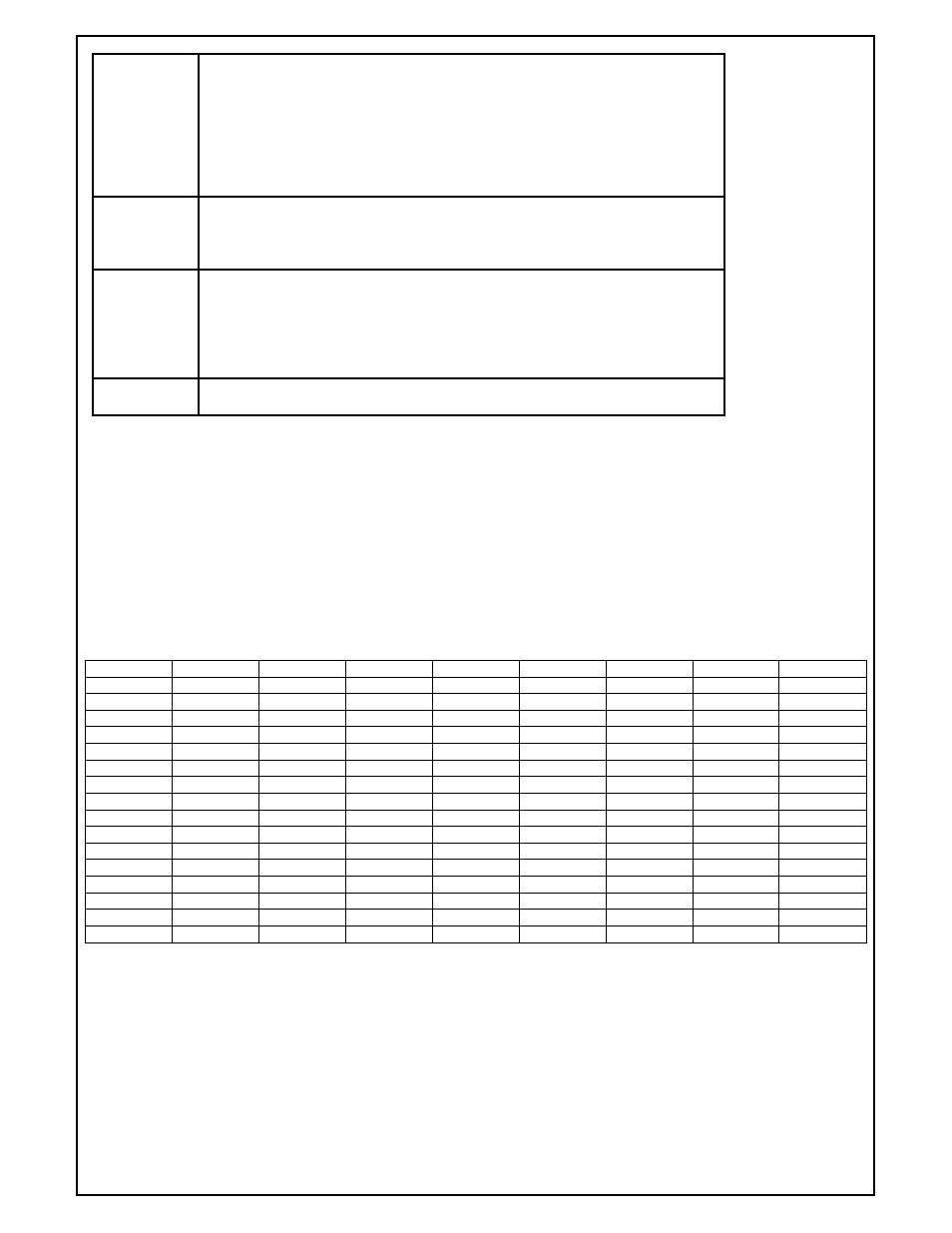
MMI Instrument Physical Addresses
The physical address is made up from the instruments address (1-15) , the Commux bank (if used) and an optional
table number. The address takes the form (CCC-TT) where CCC = channel and TT = table.
The table is optional and is only used with DUALPRO & MMIGEN type instruments. The table may be 1-31
corresponding to the Dualpro's slave tables. The channel is derived from the instrument address and the
communications bank. If a MMI UCON is used, 15 physical channels are available and the bank is always assumed
to be 0. If a MMI COMMUX is used, 120 physical channels are available, 15 on each of 8 banks.
When a MMI COMMUX is used, construct the channel address as follows:
COMMUX
BANK
1
2
3
4
5
6
7
8
ADDR 01
1
17
33
49
65
81
97
113
ADDR 02
2
18
34
50
66
82
98
114
ADDR 03
3
19
35
51
67
83
99
115
ADDR 04
4
20
36
52
68
84
100
116
ADDR 05
5
21
37
53
69
85
101
117
ADDR 06
6
22
38
54
70
86
102
118
ADDR 07
7
23
39
55
71
87
103
119
ADDR 08
8
24
40
56
72
88
104
120
ADDR 09
9
25
41
57
73
89
105
121
ADDR 10
10
26
42
58
74
90
106
122
ADDR 11
11
27
43
59
75
91
107
123
ADDR 12
12
28
44
60
76
92
108
124
ADDR 13
13
29
45
61
77
93
109
125
ADDR 14
14
30
46
62
78
94
110
126
ADDR 15
15
31
47
63
79
95
111
127
Note: If you view the physical channel as a Hex value, the left digit is (bank-1) and the right digit is the instrument
address.
e.g. bank 5 address 12 = physical channel 76 = x4C.
or physical channel 86 = x56 = bank 6 address 6.
Hex is a more convenient way of viewing the address when using a COMMUX board
.