Super Systems SuperDATA User Manual
Page 27
Super Systems Inc
Page 27 of 172
Super Data Operations Manual
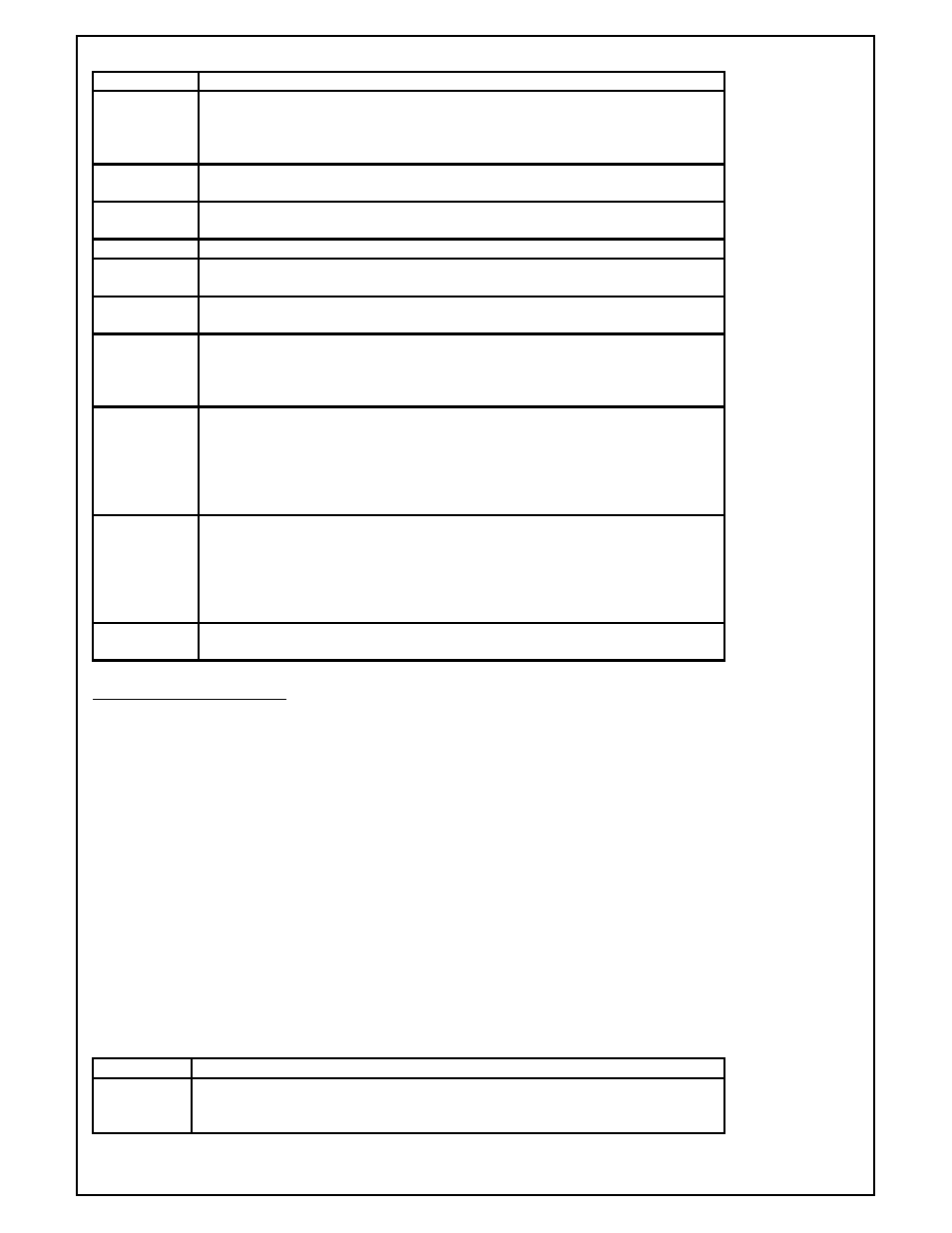
Item
Definition
C
Optional. Applies to ALL instruments. Specifies the Connection Identifier (1-8
for serial connections and 9 for Ethernet). The protocol for the connection
must match the protocol for the instrument. If not included, defaults to
Connection 1.
LLL
Required. Applies to ALL instruments.
The logical channel number assigned (1-
128).
PPP
Required. Applies to ALL instruments.
Always use physical address 0 for
system channels. Physical address is ignored.
ID
Required. Applies to ALL instruments.
The instrument ID (e.g., SSI-CON)
IP:
Required, Applies to ALL Ethernet instruments. The Ethernet address of the
instrument.
PI:
Required, Applies to ALL Ethernet instruments. The target polling interval in
seconds. Range 1-10 seconds.
NOLOG
Optional. Applies to ALL instruments.
Do not log data from this channel.
Include this when communications are required for real-time data but are not
required for historical data logging. If this is not included, the channel will be
data logged at one minute intervals.
ALM
Optional. Applies to Channels that contain bitmapped alarms.
The ALARM
configuration setup.
ALM(PAL slot, Alarm offset, Alarm Bitmap Start Slot,
Alarm ACK Bitmap Slot, Number of Bitmap Slots).
Normally this will be
configured by SSI personnel familiar with the application. If you are not sure,
do not include Bitmapped support. Invalid configurations may cause spurious
invalid alarms to be reported on RealTime and in AlarmReports.
ABC
Optional. Applies to ALL instruments.
Alarm Block Configuration .
Caution:
any specified channel can use either ALM or ABC but not both.
Allows a custom
Alarm Block Bitmap (one word) to be setup for any instrument but generally
used only for non-programmable instruments that are not capable of
maintaining alarm bitmaps. See the section on Custom Alarm Block
Configuration.
TAG
Required. Applies to ALL instruments.
Instrument name. Limited to 12
Characters with no spaces.
Generic MODBUS Instruments
[C]CH#LLL(PPP ) = "ID,[MB:xxx-yyy-t],…,[MB:xxx-yyy-t], [SMULT:SSxVALUE,…,SSxVALUE],[ALM],[
NOLOG],[ABC]" = "tag "
Examples:
5CH#24(5) = "MOD_PMC,MB:6144-30-F" = "HWCHART"
6CH#114(2) = "MMI_MOD,MB:0-10" = "MP-MOD2"
4CH#70(1) = "MOD_PMC,MB:0-50,MB:50-25" = "1RB01"
The following are examples with Ethernet comms.
9CH#24(250) = "MOD_PMC, IP:192.168.1.221, PI:1,MB:6144-30-F" = "HWCHART"
9CH#114(250) = "MMI_MOD, IP:192.168.1.221, PI:1,MB:0-10" = "MP-MOD2"
9CH#70(250) = "MOD_PMC, IP:192.168.1.221, PI:1,MB:0-50,MB:50-25" = "1RB01"
Note: Items enclosed in brackets [ ] are optional but may be required for certain instrument types.
Item
Definition
C
Optional. Applies to ALL instruments. Specifies the Connection Identifier (1-8
for serial connections and 9 for Ethernet). The protocol for the connection must
match the protocol for the instrument. If not included, defaults to Connection