2 main analog characteristics – Sundance SMT321 User Manual
Page 9
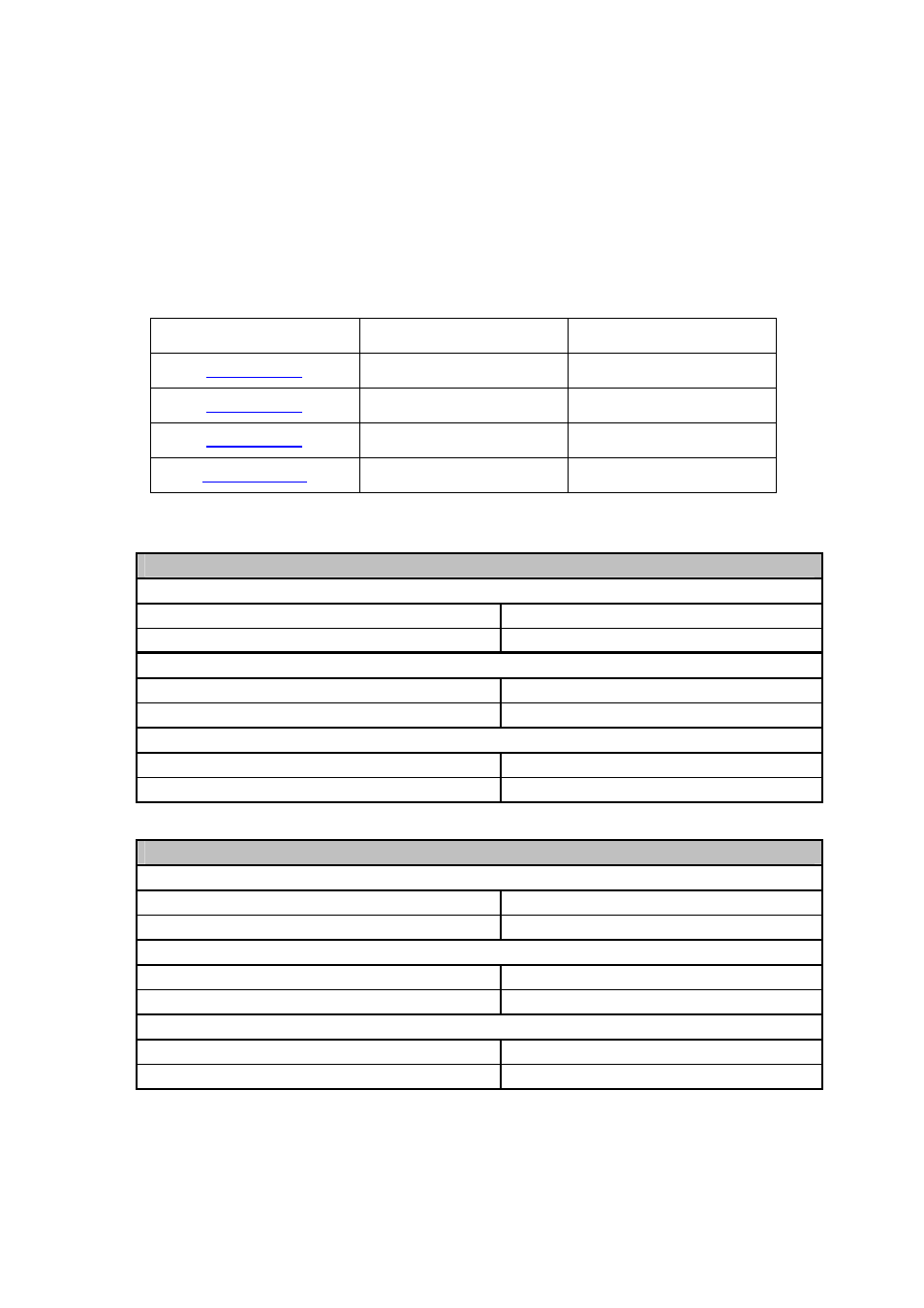
2.2 Main Analog Characteristics
The SMT321 comes in two different configurations. The main differences on the two
modules are clock generation and analog signal generation. Table 2 shows the
configuration of the lower frequencies module. Table 1 shows the frequencies attainable
by the various VCO’s implemented on the SMT321. The high frequency configuration
board is shown in Table 3.
VCO Model Number
Minimum Frequency
Maximum Frequency
UMS-150-A16
75MHz
150MHz
UMS-300-A16
150MHz
300MHz
UMS-535-A16
300MHz
535MHz
UMS-1000-A16
500MHz
1000MHz
Table 1. VCO models frequency ranges.
SMT321 (Lower Frequencies Configuration) Output
Triggers (LVPECL)
Channel A
75Hz – 5MHz
Channel B
75Hz – 5MHz
Analog Signals (Analog)
Channel A
75MHz – 150MHz
Channel B
150MHz – 300MHz
Clock Signals (LVPECL)
Channel A
25MHz – 400MHz
Channel B
25MHz – 400MHz
Table 2. Analog characteristics of SMT321 low frequency configuration.
SMT321 (Higher Frequencies Configuration) Output
Triggers (LVPECL)
Channel A
75Hz – 5MHz
Channel B
75Hz – 5MHz
Analog Signals (Analog)
Channel A
300MHz – 535MHz
Channel B
500MHz – 1000MHz
Clock Signals (LVPECL)
Channel A
50MHz – 950MHz
Channel B
50MHz – 950MHz
Table 3. Analog characteristics of SMT321 high frequency configuration.