2 reading and writing registers – Sundance SMT321 User Manual
Page 22
the appropriate settings be implemented. The first four bits indicate the operation which
must be preformed. There are four operations:
•
Comport Reset (bit sequence: 1111)
•
Loop back Mode (bit sequence: 0000)
•
Comport Register Write Command (bit sequence: 0001)
•
Comport Register Read Command (bit sequence: 0010)
The next 12 bits specifies the register to read or write. In the first two commands (Reset
and Loop back) the rest of the packet is NO CARES.
The read command packet only needs the first 2 bytes to read a specific register the last
two bytes are NO CARES.
Write commands use the whole packet, with the last 2 bytes being the data to be written
to the specific register.
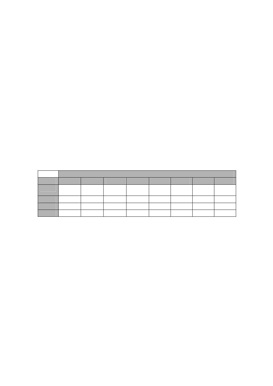
This structure is illustrated in the following figure:
Byte Content
Byte
Bit 7
Bit 6
Bit 5
Bit 4
Bit 3
Bit 2
Bit 1
Bit 0
0
Command
3
Command
2
Command
1
Command
0
Address
11
Address
10
Address
9
Address
8
1
Address 7
Address 6
Address 5
Address 4
Address 3
Address 2
Address 1
Address 0
2
Data 15
Data 14
Data 13
Data 12
Data 11
Data 10
Data 9
Data 8
3
Data 7
Data 6
Data 5
Data 4
Data 3
Data 2
Data 1
Data 0
Figure 11. Setup Packet Structure.
4.2 Reading and Writing Registers
Control packets are sent to the SMT321 over Comport 3. This is a uni-directional
interface and data can only be sent to the SMT321 over Comport 3. Comport 0 is used
to read control information back from the SMT321. Comport 0 is thus also a uni-
directional interface going from the SMT321 to the system host. Data is read by issuing
a ‘Read Request’ control packet containing the address to be read over Comport 3. The
SMT321 will collect the required data and send a ‘Read Packet’ out over Comport 0
containing the requested data. The format of a ‘Read Packet’ is the same as that of a
write packet.