6 msp functionality, 7 trigger output – Sundance SMT321 User Manual
Page 14
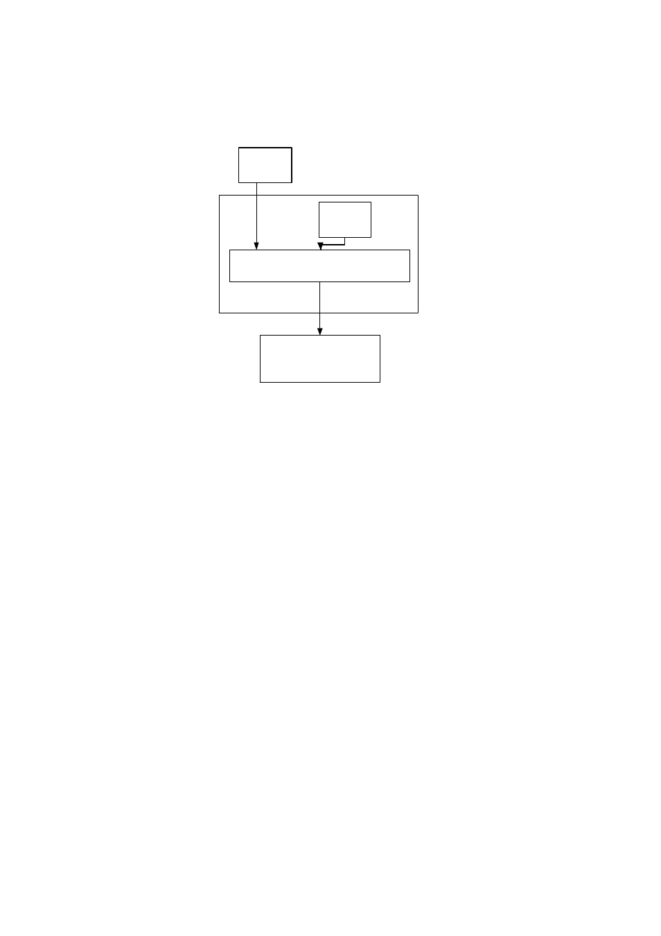
Reset Control
POR Reset
TIM
Connector
Reset
FPGA
MSP430
Fpga
nReset
Figure 4. Reset Generation and Distribution.
2.6 MSP Functionality
The MSP430 implements analog control functionality that is difficult to implement in the
FPGA. The microprocessor
•
Controls the power start-up sequence
•
Controls the reset structure on the module
•
Read the temperature from the MAXIM temperature sensor
•
Read the serial number from the MAXIM silicon serial number package
The measured information is passed on to the FPGA over a custom bus implementation
between the microprocessor and the FPGA
2.7 Trigger Output
As discussed in the internal data path of the FPGA the triggers operate in two channels
and each channel has three setup registers. Each channel can have a continuous trigger
or a single pulse generated in one channel depending on the multiplexer.
The user configures the triggers via the comports which sets up the trigger registers. The
triggers are made from the system clock (10MHz) which is then scaled by using
counters. Thus if the triggers are set up for a high time of one clock and a low time of
one clock it attains a frequency of 5MHz which is the maximum trigger frequency