3 trigger control registers – Sundance SMT321 User Manual
Page 25
Output division on the clock synthesizers is achieved by the two output division bits
found in the first byte of the clock control registers. There configurations are shown in
table 8.
Table 8. Output division configurations.
The M count bits are used to configure the clock output frequency given all the
constraints set by the hardware and the clock setup bits. The nine bits can be
programmed with any value from 200 – 400 (475 for higher frequency board). All the
setup bits are then used to calculate the output with the following equation.
FXTAL = 16MHz (external oscillator)
N = Value in decimal, set up by the division bits.
M = Value in decimal, set up by the M count bits.
Figure 13. Clock output equation.
For more information refer to the Micrel datasheets [2].
4.4.3 Trigger Control Registers
Registers 0x020 – 0x025 are used for trigger and pulse shaping. Any value from 0 to
65535 (16 bits) can be written into these registers which shapes the triggers and pulses
into high and low times. There are six registers but only 3 influence one channel. The
Trigger A High Register, Trigger B High Register, One Pulse A High Register and One
Pulse B High Register are all high counts (counted in system clocks) of the triggers. Both
the continuous trigger registers (Trigger A High Register and Trigger B High Register)
and the pulse registers (One Pulse A High Register and One Pulse B High Register)
starts counting from one.
Thus if for example the value 2 is written into Trigger A High Register and One Pulse A
High Register the continuous trigger will be high for 2 system clocks and the pulse will
be high for 2 system clocks. The two low registers only have an influence on the
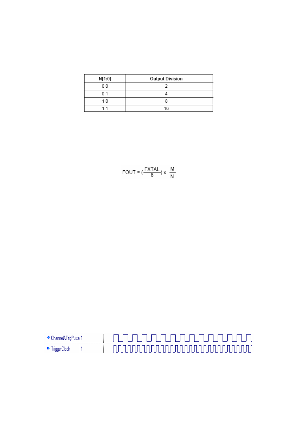
continuous triggers which also needs a low time to shape the trigger. A 1 high 1 low (1 in
high register and 1 in low register) would generate a continuous trigger shown in figure
14.
Figure 14. Trigger with 1 clock high and 1 clock low.