Sundance SMT391-VP User Manual
Page 37
Version 1.3
Page 37 of 41
SMT391-VP User Manual
Figure 26 – Clock Synthesizer Division Setup.
The M count bits are used to configure the clock output frequency given all the
constraints set by the hardware and the clock setup bits. The nine bits can be
programmed with any value from 200 – 475. All the setup bits are then used to
calculate the output with the following equation.
FXTAL = 16MHz (external oscillator)
N = Value in decimal, set up by the division bits.
M = Value in decimal, set up by the M count bits.
Figure 27 – Clock Synthesizer Frequency Calculation.
For more information refer to the Micrel datasheets of this part.
ADC interface
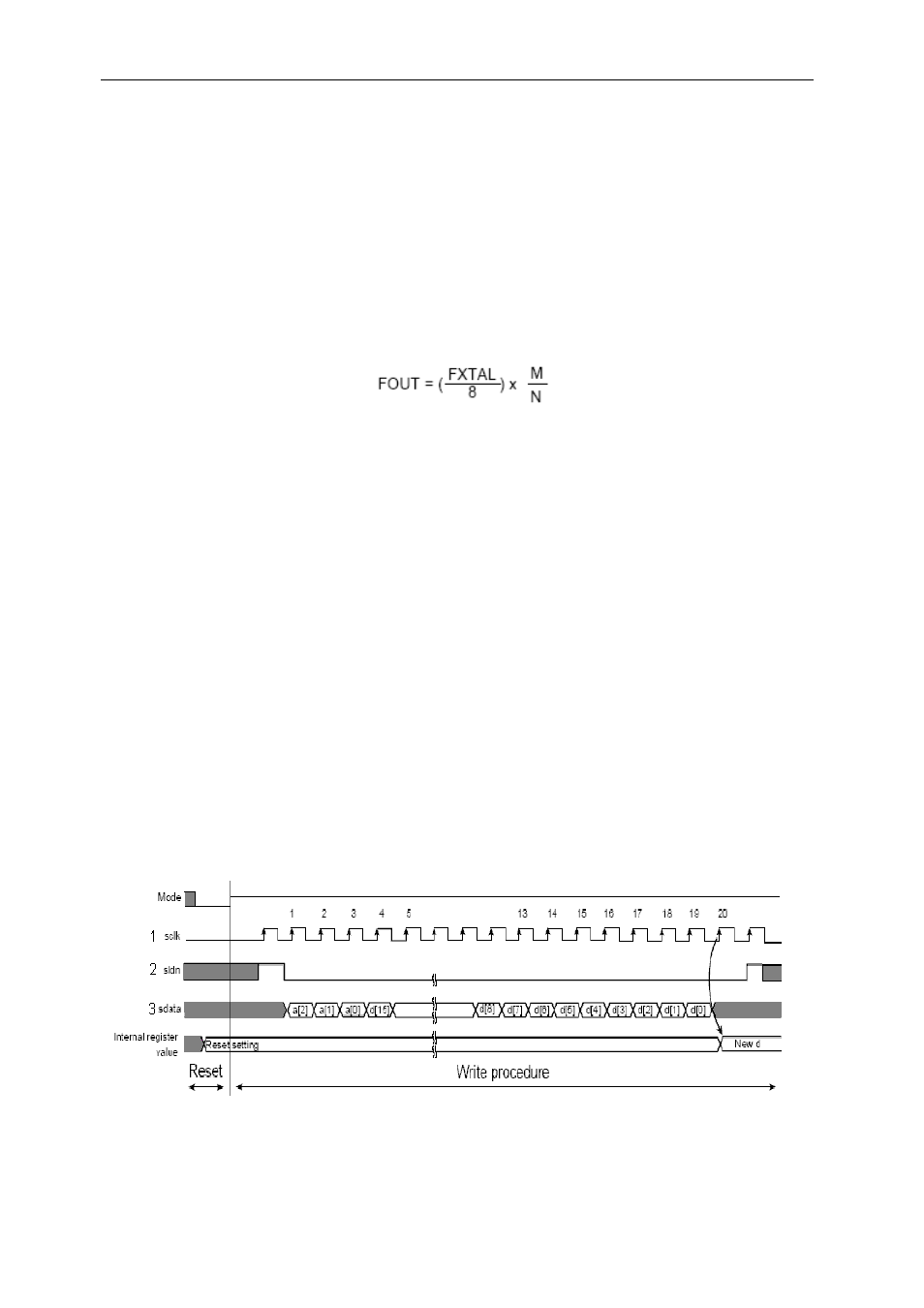
The 3-wire serial interface gives write-only access to as many as 8 different internal
registers of up to 16 bits each (registers in the ADC). The ADC input format is always
fixed with 3 bits of register address followed by 16 bits of data. The data and address
are entered with the Most Significant Bit (MSB) first.
The following figure shows the timing diagram for the 3 wire setup interface of the
ADC. The three wires are labelled 1 – 3.