Sundance SMT391-VP User Manual
Page 29
Version 1.3
Page 29 of 41
SMT391-VP User Manual
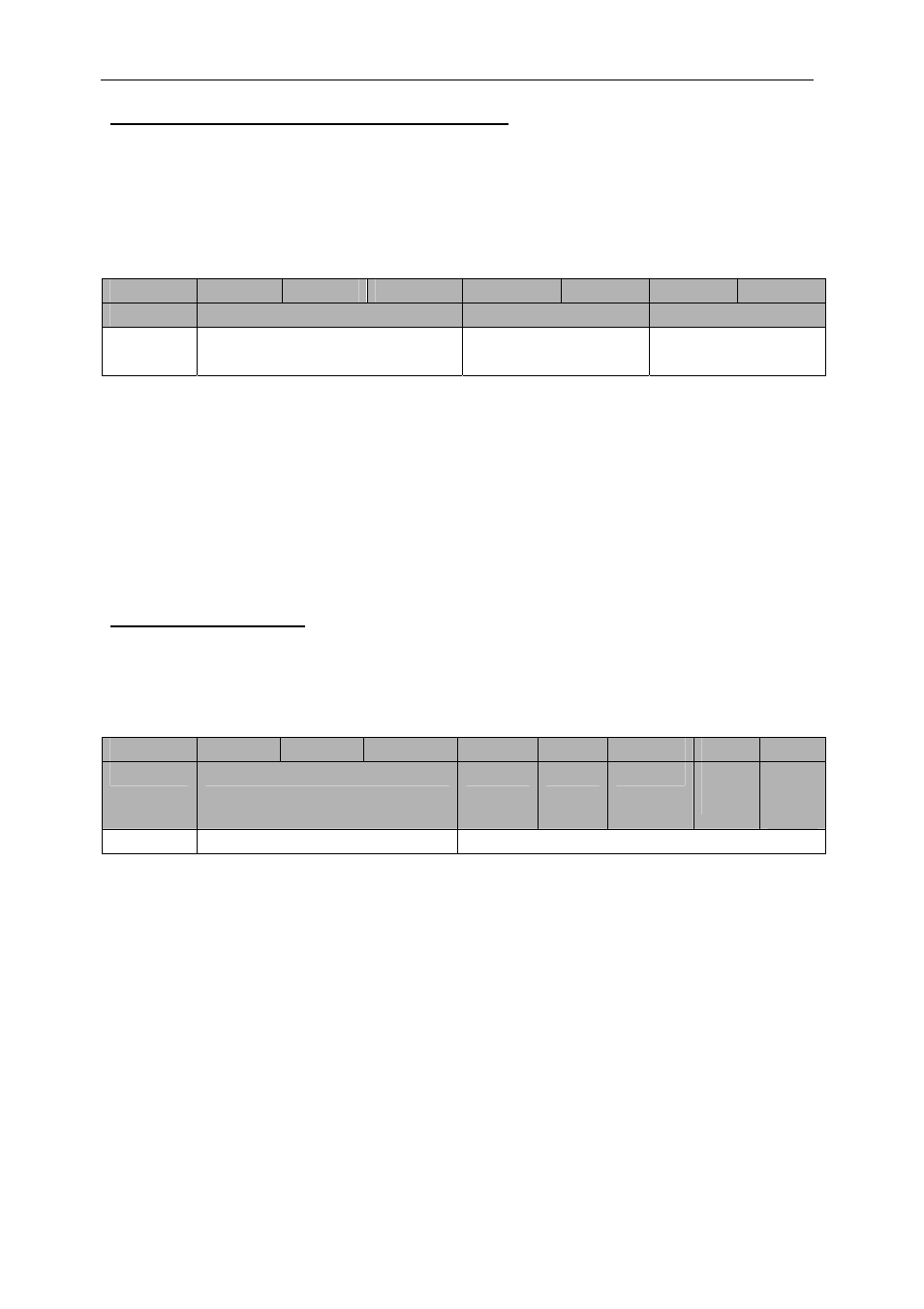
ADC Setup Registers (Write Add 0x80B, 0x80C)
These registers configure the internal functionality of the ADC on the SMT391. There
are two registers – a data register and an address registers. The address register
must be set up before the data register. Once the data register is written to the data
and address information contained in the two registers will be transferred to the ADC
over a serial interface.
31 .. 28
27 .. 24
23 .. 20
19 .. 16
15 .. 12
11 .. 8
7 .. 4
3 .. 0
Command
Address
Data MSB
Data LSB
0x1
0x1
0x80B
0x80C
Smt391AdcCntrlAddress
Smt391AdcCntrlData
Smt391AdcCntrlAddress
Smt391AdcCntrlData
Figure 15 – ADC Setup Registers (Write Only).
The addresses to use when accessing Smt391AdcCntrlAddress register is the are
described in the ADC data sheet along with the matching data to write in the
Smt391AdcCntrlData.
For more details about the ADC configuration refer to the appendix section.
Trigger register (0x042)
It is possible to trigger the acquisition of the data coming form the ADC using an
external trigger signal. This register allows configuring the SMT391-VP to use this
trigger.
31 .. 28
27 .. 24
23 .. 20
19 .. 16
9
8
7 .. 2
1
0
Command
Address
Reserved
Reserved
Reserved
external
trigger
level
external
trigger
enable /
disable
0x1 0x042
TRIGGER_REG
Bit 0: ‘1’ enable the external trigger. The acquisition will start only when a trigger is
received.
‘0’ disable the external trigger. The acquisition will start as soon as the ADC
interface is removed from reset (bit 1 of the reset register)
Bit 1: specify the level at which the trigger is active.
‘0’: trigger active low.
‘1’: trigger active high.