Sundance SMT391-VP User Manual
Page 34
Version 1.3
Page 34 of 41
SMT391-VP User Manual
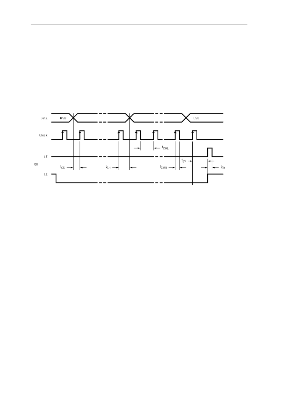
First off the LE line is pulled low and then the MSB of data is loaded onto the Data
line. The Clock line is then driven high and low and a new Data line value is clocked
into the Pll on each rising edge of the Clock line. The Data line is driven with the
registers setup and the Clock line driven high and low until the Data line has reached
the LSB. To end the sequence the LE line is pulled high.
There are two ways to operate the LE line as also shown in the figure below. The
figure also explains how to configure the device.
Figure 22 – PLL Configuration Sequence.
The figure below explains the state diagram residing in the firmware design
(SMT338-VP’s Fpga). This design ultimately executes the procedures explained in
the previous figures and paragraph.
- SMT107 (16 pages)
- SMT6035 v.2.2 (39 pages)
- SMT6012 v.4.6 (22 pages)
- FC100 (12 pages)
- FC108 v.1.1 (10 pages)
- SMT6065 v.4.0 (45 pages)
- FFT v.2.1 (19 pages)
- SMT111 (18 pages)
- SMT118LT (10 pages)
- SMT118 (20 pages)
- SMT123-SHB (13 pages)
- SMT128 (15 pages)
- SMT145 (18 pages)
- SMT148 (35 pages)
- SMT130 v.1.0 (46 pages)
- SMT148FX (48 pages)
- SMT310Q (55 pages)
- PARS (70 pages)
- SMT166-FMC (52 pages)
- SMT166 (44 pages)
- SMT300Q v.1.6 (61 pages)
- SMT310 v.1.6 (50 pages)
- SMT317 (24 pages)
- SMT326v2 (24 pages)
- SMT338 (19 pages)
- SMT349 (32 pages)
- SMT339 v.1.3 (27 pages)
- SMT338-VP (22 pages)
- SMT358 (25 pages)
- SMT351T (37 pages)
- SMT351 (25 pages)
- SMT350 (45 pages)
- SMT362 (30 pages)
- SMT365G (23 pages)
- SMT364 (37 pages)
- SMT373 (15 pages)
- SMT368 (24 pages)
- SMT370v3 (46 pages)
- SMT377 (22 pages)
- SMT381 2007 (31 pages)
- SMT381-VP (81 pages)
- SMT387 (42 pages)
- SMT391 (18 pages)
- SMT384 (47 pages)
- SMT390-VP (55 pages)