Sundance SMT391-VP User Manual
Page 35
Version 1.3
Page 35 of 41
SMT391-VP User Manual
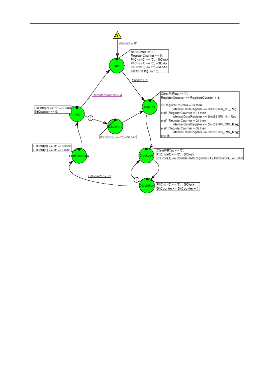
Figure 23 – State Machine Driving the PLL Serial Interface.
Clock synthesiser interface
A three wire uni-directional control interface is implemented between the FPGA of the
SMT338-VP and the clock synthesizer present on the SMT391.
One 16 bit register in the SMT338-VP firmware is used for the setup of the clock
synthesizer. The data word needed for the setup of the synthesizer is only 14 bits
long - thus the 16 bit register is sufficient to receive data from the Comport in one
write cycle from the Host. When the Comport receives the data for the clock
synthesizer register it configures the internal firmware register accordingly and
asserts the enable pin on the Clock Synthesizer State Machine.
The Clock Synthesizer State Machine generates the handshaking signals to clock
data into the synthesizer. The synthesizer then generates an output clock depending
on the setup given by the user. The output of the Synthesizer is a LVPECL signal.