Sundance SMT391-VP User Manual
Page 31
Version 1.3
Page 31 of 41
SMT391-VP User Manual
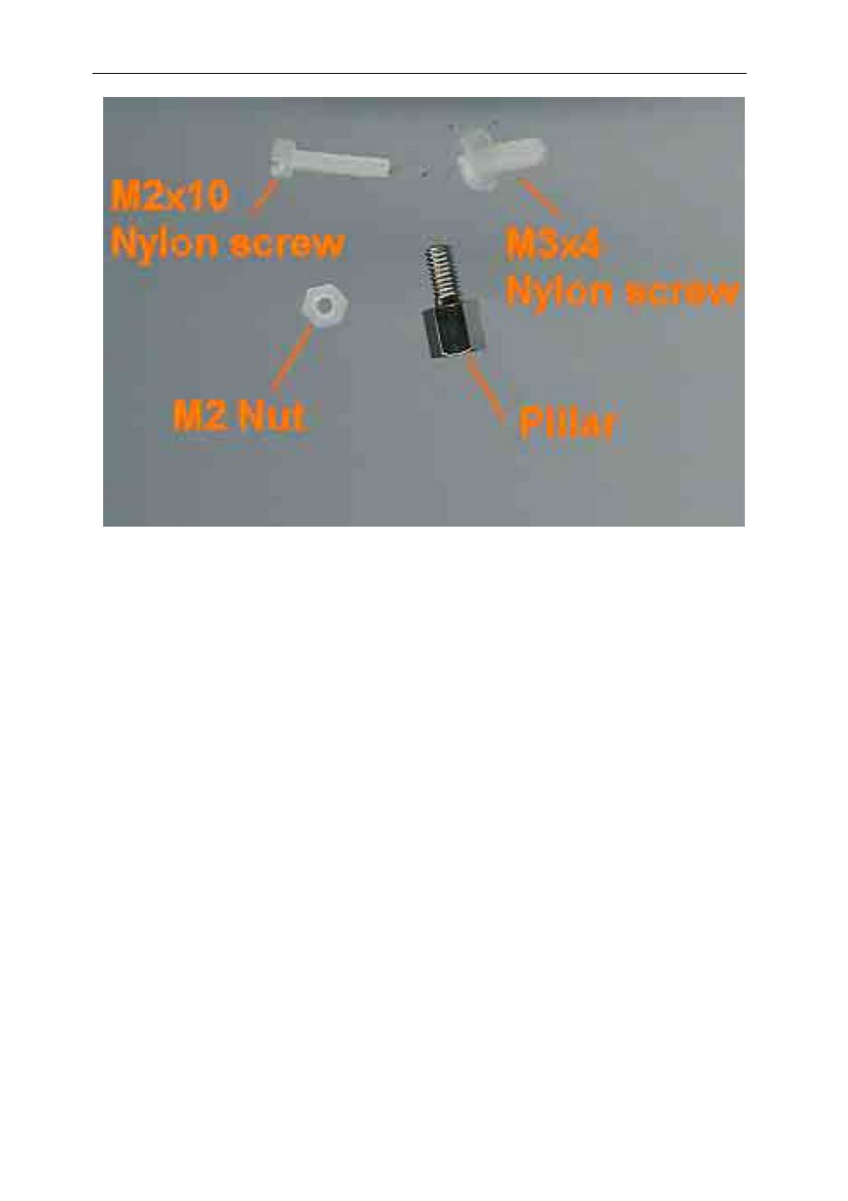
Figure 17 – Components Used to Connect the SMT391 to the SMT338-VP.
1) First fit two Nylon screws (M2 x 10), pointing out (the head of the screws on
the bottom side of the SMT338-VP).
2) Then fit four M2 nuts on each screw.
3) Place the SMT338-VP on the second TIM site (TIM 1 is for the Host) of a
Sundance carrier (like the SMT310Q)
4) Fit the two metal pillars to the TIM mounting holes to give the SMT338-VP
3.3V from the carrier.
5) Place the SMT391-VP on top of the SMT338-VP and make sure that both
modules fit firmly (the SMT391 does not need 3.3V of it’s mounting hole).
6) Fit two M2 nuts on the Nylon screws and two M3x4 screws in the 3.3V pillars.
7) Connect Comport3 of the SMT391-VP to an available Comport on the Host
module (eg Comport 0).
- SMT107 (16 pages)
- SMT6035 v.2.2 (39 pages)
- SMT6012 v.4.6 (22 pages)
- FC100 (12 pages)
- FC108 v.1.1 (10 pages)
- SMT6065 v.4.0 (45 pages)
- FFT v.2.1 (19 pages)
- SMT111 (18 pages)
- SMT118LT (10 pages)
- SMT118 (20 pages)
- SMT123-SHB (13 pages)
- SMT128 (15 pages)
- SMT145 (18 pages)
- SMT148 (35 pages)
- SMT130 v.1.0 (46 pages)
- SMT148FX (48 pages)
- SMT310Q (55 pages)
- PARS (70 pages)
- SMT166-FMC (52 pages)
- SMT166 (44 pages)
- SMT300Q v.1.6 (61 pages)
- SMT310 v.1.6 (50 pages)
- SMT317 (24 pages)
- SMT326v2 (24 pages)
- SMT338 (19 pages)
- SMT349 (32 pages)
- SMT339 v.1.3 (27 pages)
- SMT338-VP (22 pages)
- SMT358 (25 pages)
- SMT351T (37 pages)
- SMT351 (25 pages)
- SMT350 (45 pages)
- SMT362 (30 pages)
- SMT365G (23 pages)
- SMT364 (37 pages)
- SMT373 (15 pages)
- SMT368 (24 pages)
- SMT370v3 (46 pages)
- SMT377 (22 pages)
- SMT381 2007 (31 pages)
- SMT381-VP (81 pages)
- SMT387 (42 pages)
- SMT391 (18 pages)
- SMT384 (47 pages)
- SMT390-VP (55 pages)