Appendix – Sundance SMT391-VP User Manual
Page 33
Version 1.3
Page 33 of 41
SMT391-VP User Manual
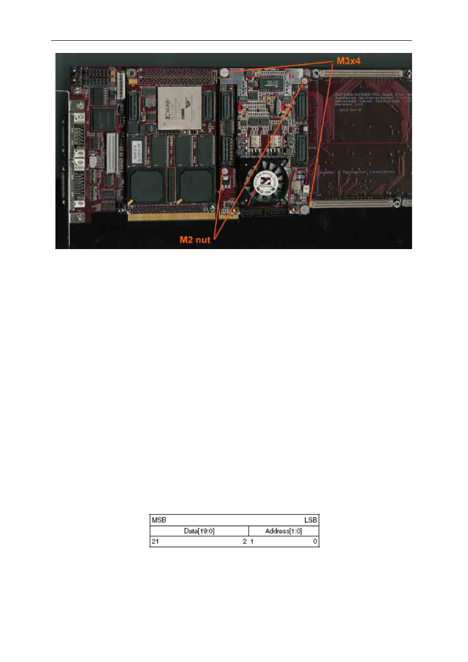
Figure 20 – Connecting the SMT391 to the SMT338-VP
Configuring the FPGA
A microcontroller MSP430 is connected to the comport 3 of the SMT391-VP. The
MSP430 received the bitstream of the FPGA from the comport 3 and then configures
the FPGA with it.
Refer to the SMT6500 user guide for the details of the configuration of the FPGA.
Appendix
PLL (LMX2330U) interface
The PLL 22-bit shift register is loaded via a microwire interface. This interface
consists of 3 wires. The shift register consists of a 20-bit Data[19:0] Field and a 2-bit
Address[1:0] Field. The Address Field is used to decode the internal control register
address. When LE transitions HIGH, data stored in the shift register is loaded into
one of 4 control registers depending on the state of the address bits. The MSB of
Data is loaded in first. The register is shown in the following figure.
Figure 21 – Register Setup for PLL.
- SMT107 (16 pages)
- SMT6035 v.2.2 (39 pages)
- SMT6012 v.4.6 (22 pages)
- FC100 (12 pages)
- FC108 v.1.1 (10 pages)
- SMT6065 v.4.0 (45 pages)
- FFT v.2.1 (19 pages)
- SMT111 (18 pages)
- SMT118LT (10 pages)
- SMT118 (20 pages)
- SMT123-SHB (13 pages)
- SMT128 (15 pages)
- SMT145 (18 pages)
- SMT148 (35 pages)
- SMT130 v.1.0 (46 pages)
- SMT148FX (48 pages)
- SMT310Q (55 pages)
- PARS (70 pages)
- SMT166-FMC (52 pages)
- SMT166 (44 pages)
- SMT300Q v.1.6 (61 pages)
- SMT310 v.1.6 (50 pages)
- SMT317 (24 pages)
- SMT326v2 (24 pages)
- SMT338 (19 pages)
- SMT349 (32 pages)
- SMT339 v.1.3 (27 pages)
- SMT338-VP (22 pages)
- SMT358 (25 pages)
- SMT351T (37 pages)
- SMT351 (25 pages)
- SMT350 (45 pages)
- SMT362 (30 pages)
- SMT365G (23 pages)
- SMT364 (37 pages)
- SMT373 (15 pages)
- SMT368 (24 pages)
- SMT370v3 (46 pages)
- SMT377 (22 pages)
- SMT381 2007 (31 pages)
- SMT381-VP (81 pages)
- SMT387 (42 pages)
- SMT391 (18 pages)
- SMT384 (47 pages)
- SMT390-VP (55 pages)