Setup guide, Product orientation – SoundTraxx SurroundTraxx User Manual
Page 12
SurroundTraxx User’s Guide
Setup Guide Page 1:6
SurroundTraxx User’s Guide
Setup Guide Page 1:7
Setup Guide
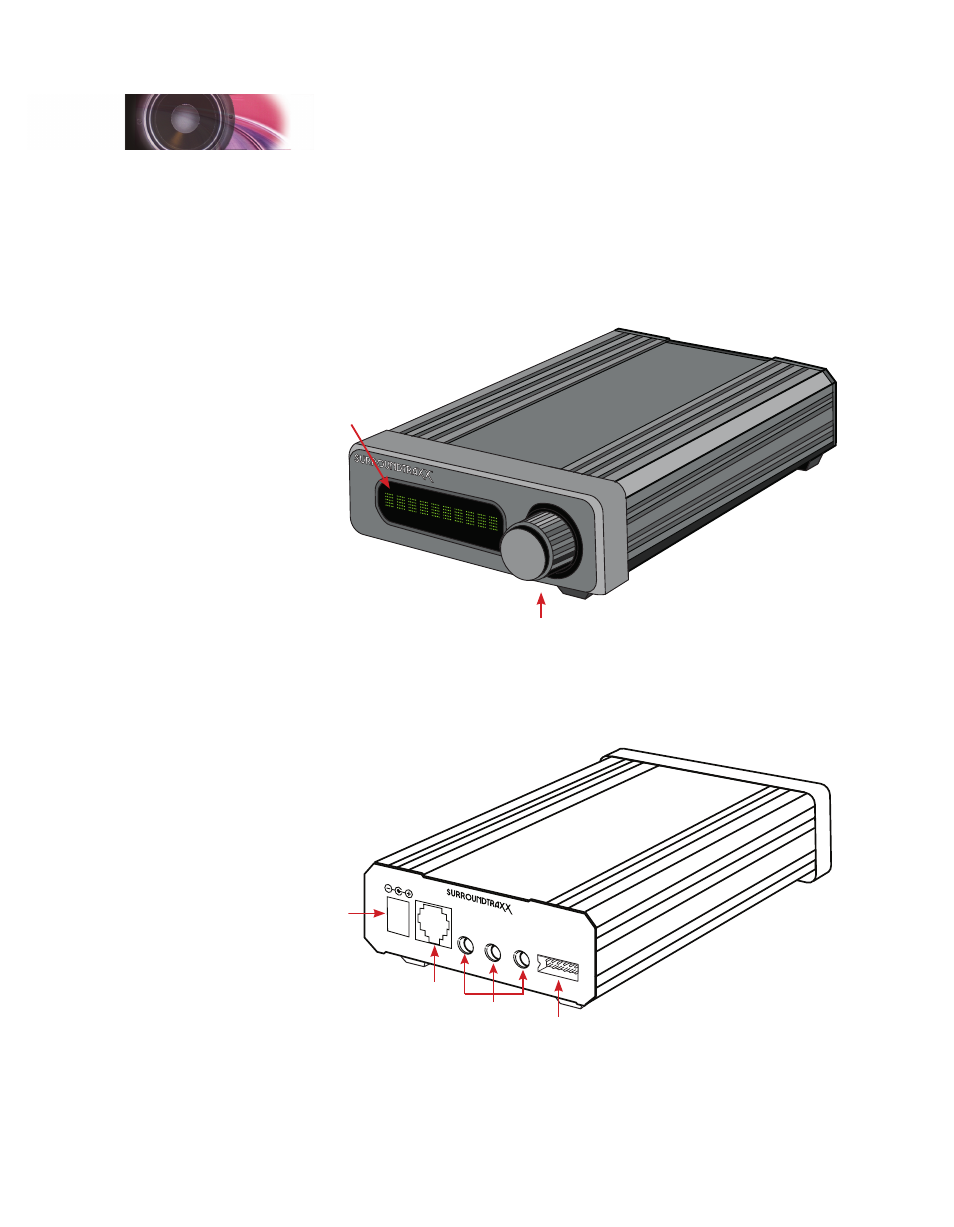
Product Orientation
On the front of your SurroundTraxx system you will notice a 10-digit LED
display and a control knob that you can both push in or turn. This control
knob is how you will access the different menu options you will explore in
later sections of this manual. The display shows both what we call System
Monitor Mode (the default mode when SurroundTraxx is powered up and
operating) as well as the different menus and selections.
®
Control Knob
LED Display
On the back of your SurroundTraxx system you will see the different outputs
for wiring everything needed to make it work. Starting from left to right is
the input for the power supply. Next, is the network cable input to connect
the SurroundTraxx system to the layout LocoNet system that is tied to your
command station, block detectors, and cab.
INPUT
:
5VDC,
3A
POWER
NETW
ORK
SPEAKERS
LINE LEVEL OUT
DIGITAL
SOUND
PROCES
SOR
SOUNDT
RAXX
Durango
, CO 813
01
USA
1/2
3/4
5/6
®
Network
Power
Input
Speaker
Harness
Audio Out
Adjacent to the LocoNet input are three line level output jacks that
correspond to the six different sound channels found on SurroundTraxx.