4 reset, 5 status flags, 6 actions – Sensoray 2600 User Manual
Page 77
2600 Family Instruction Manual
72
Chapter 12 : Model 2653 SSR Module
states, which is delayed 10 milliseconds by the debounce
function.
12.4 Reset
Upon module reset, all channels default to the Standard
operating mode and all SSR output drivers default to the
inactive state. A 2653 module will experience a module reset
in response to any of the following conditions:
• Module power-up.
• Watchdog time-out due to soft or hard fault.
• SoftReset or HardReset action request from the client.
• Communication time-out, which will occur if the client
fails to communicate with the 2653 module within a
programmable communication watchdog interval.
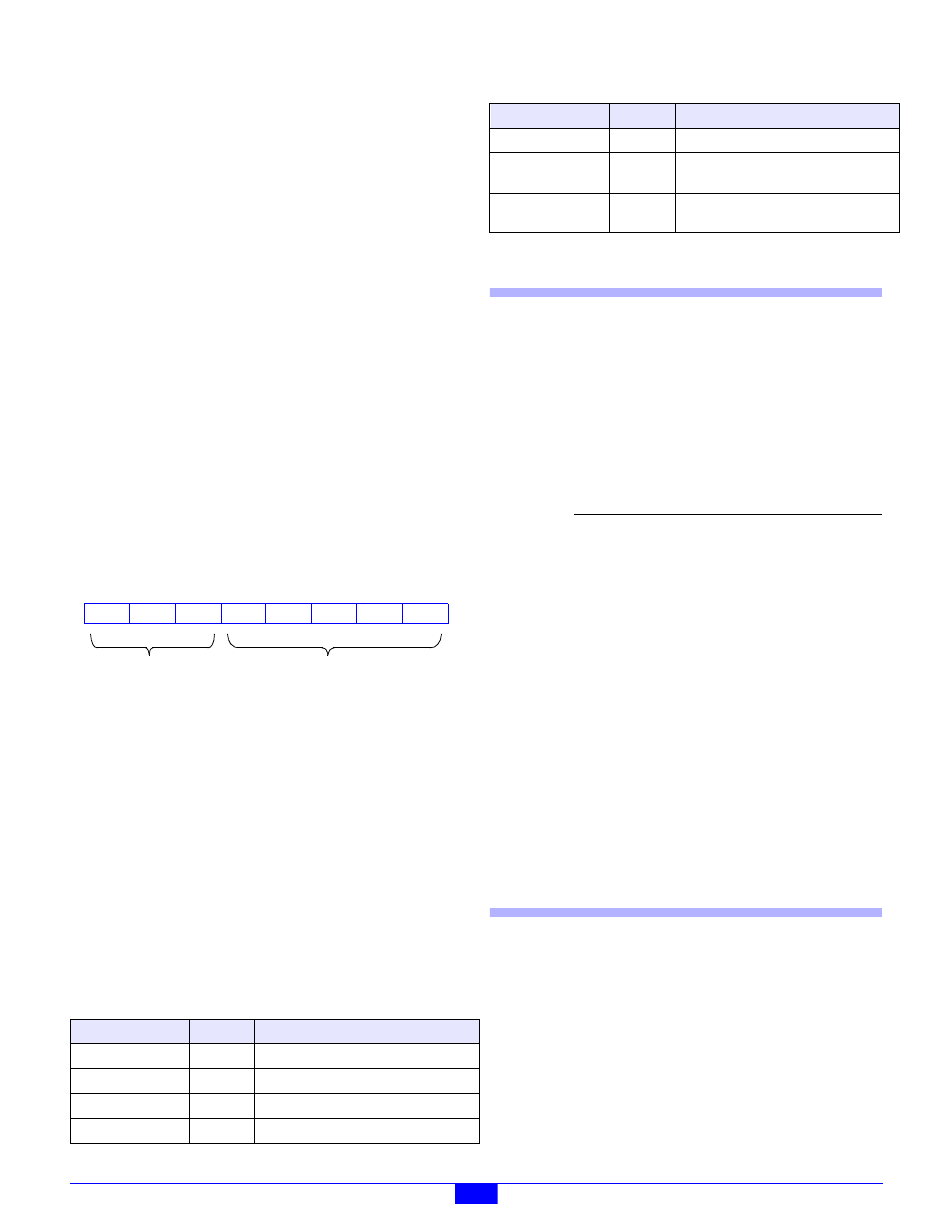
12.5 Status Flags
In addition to the standard flag bits that are common to all
IOMs (see Section 3.4.1), the status byte returned by a 2653
module includes one fault flag that is specific to 2653 module
types. The 2653 status byte is structured as shown in Figure
67.
Figure 67: 2653 Status Byte
STRM
- Active-high bit flag that indicates an error was detected
in the serial data stream that is used to control the SSR output
drivers. This flag can be cleared by invoking a ResetFlags
action.
12.6 Actions
This section describes the programmable actions that are
supported exclusively by the 2653 module. These actions may
be employed, in any sequence or combination, in MCmd action
lists.
2653 modules support all of the common actions that are
universally recognized by all IOMs, such as HardReset,
SoftReset
, etc. Refer to Chapter 5 for details.
Note: Model 2610 has a maximum MRsp size of eleven bytes.
12.6.1 GetInputs
Function
Returns the debounced, physical states of all SSR
channels.
Opcode
0x00
Command none
Response
(S<7:0>),(S<15:8>)
Notes
The returned state values represent the
debounced, physical states of all SSR channels.
Because the inputs are sampled every 2
milliseconds, and the debounce period is 10
milliseconds, the returned state values will all
have an age ranging from 10 to 12 milliseconds,
plus any network communication latency.
Note that the physical states of all SSR channels
are returned, regardless of their respective
operating modes.
12.6.2 GetOutputs
Function
Returns the programmed output driver states of
all SSR channels. Note that the programmed
states may match the physical states (that would
be returned by GetInputs) because some
channels may be driven by external signal
sources. In the case of channels that have been
configured for the PWM mode, this function
returns indeterminate values.
Opcode
0x01
Table 40: Summary of 2653 Module Actions
Command
Opcode
Function
GetInputs
0x00
Return physical channel states.
GetOutputs
0x01
Return programmed channel states.
SetOutputs
0x02
Program output driver states.
SetModes
0x03
Set channel operating modes.
7
RST
6
CERR
5
4
HRST
3
0
2
1
0
0
0
2652-specific
Standard
STRM
0
GetModes
0x04
Return channel operating modes.
SetPwmRatio
0x05
Program PWM duty cycle and period
for one channel.
GetPwmRatio
0x06
Return PWM duty cycle and period
for one channel.
Parameter
Function
S[]
Byte array containing 16 bit flags that
represent the debounced, physical
states of all SSR channels. Each bit is
associated with one SSR channel. For
example, bit 14 is associated with SSR
channel 14. Any bit set to one indicates
the associated channel is set to the
active state; any bit set to zero indicates
the channel is set to the inactive state.
Table 40: Summary of 2653 Module Actions
Command
Opcode
Function