1 introduction, 2 analog outputs, 3 analog inputs – Sensoray 2600 User Manual
Page 34: 1 conversion process
2600 Family Instruction Manual
29
Chapter 6 : Model 2608 Analog I/O Module
Chapter 6: Model 2608 Analog I/O Module
6.1 Introduction
The model 2608 module is a smart I/O module (IOM) that has
16 fully differential analog input (AIN) channels and either
zero (2608-0), four (2608-4) or eight (2608-8) analog output
(AOUT) channels. By means of a single Cat-5 cable, the 2608
may be connected to any IOM port on a model 2601 main
module (MM).
Analog I/O channels are referenced by channel number. AIN
channel numbers range from 0 to 15, and AOUT channel
numbers range from 0 to 3.
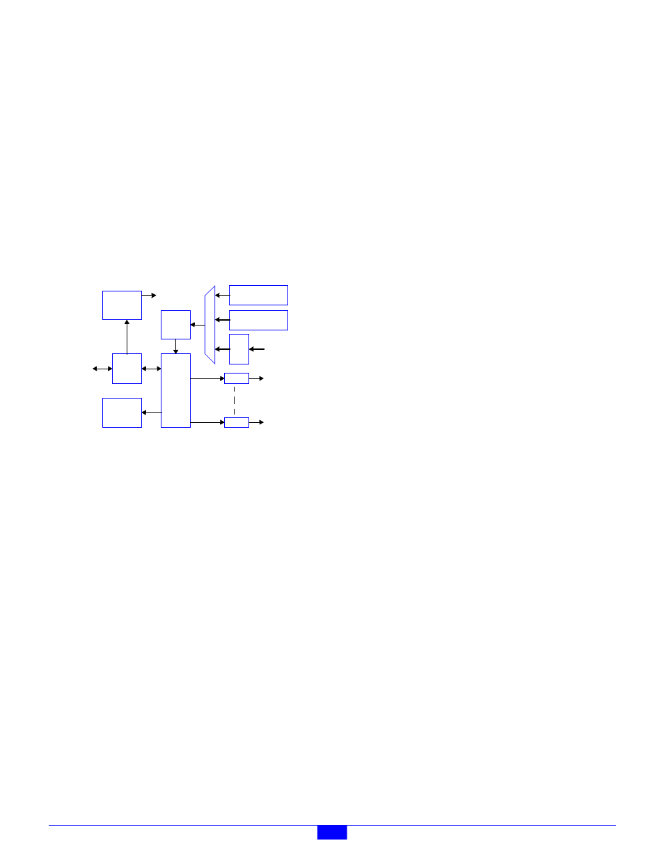
Figure 32: Model 2608 Block Diagram
Analog input and output subsystems include special circuitry
that implements fully electronic calibration. Excellent
long-term accuracy is achieved through the combination of
high quality on-board reference standards and the total absence
of mechanical trims. Calibration constants are stored on-board
in non-volatile memory so that modules can be changed out
without the need for system-level recalibration.
Module connectors are optimized for direct connection to field
wiring, in most cases eliminating the need for external field
wiring termination systems. All field wiring is attached
directly to the module by means of pluggable connectors so
that downtime will be minimized should it become necessary
to replace a module.
The entire module is automatically reset by a built-in watchdog
timer if an internal fault develops. Also, the module
automatically resets if the MM fails to communicate within a
programmable time interval.
Diagnostic LEDs include Power, Heartbeat, and
communication status. A self-test is performed automatically
at power-on and reset, and any detected fault conditions are
displayed on the status indicators.
A high-efficiency, on-board power supply produces all
required operating voltages from a single 24VDC source,
which is obtained from the MM via the module’s IOM port.
Test points are provided for all power supply voltages and
analog I/O signals.
6.2 Analog Outputs
AOUT channels generate programmed voltages spanning the
range from -10V to +10V. Each AOUT channel employs a
dedicated digital-to-analog converter (DAC) with an effective
resolution of 15 bits, minimum. All AOUT channels default to
zero volts out upon reset or power-up.
Each AOUT channel is provided with a connector that includes
circuits for analog output, remote output sense, output return,
and power for external circuitry such as active sensors.
6.3 Analog Inputs
Analog inputs utilize fully differential signal paths to help
maintain measurement accuracy in electrically noisy
environments. AIN channels may be independently software
configured for either a ±10V or ±100mV input range.
Various reference standards, as well as thermocouple reference
junction temperature sensors, are built into the model 2608.
All of these references occupy dedicated input channels so as
to not consume application input channels.
AIN signals connect to the module by means of pluggable
terminal blocks. Each channel is provided with terminal block
circuits for the differential analog input signal pair and power
out to external signal-producing devices.
6.3.1 Conversion Process
A 10 µsec, 16-bit ADC is used to digitize all external input
signals and the internal references. Data conversions are
performed periodically, at two millisecond intervals,
independent of client activity.
During each two-millisecond (mS) interval, all 16 external
inputs and all internal references are acquired. External inputs
are acquired sequentially in order of increasing channel
number, beginning with channel 0. The following process is
applied to each external input:
• The analog input signal is routed to the ADC and gain is
applied as appropriate.
• The ADC’s input signal path is given time to settle.
• The input is digitized four times in rapid succession, and
the results are averaged to produce a snapshot value. The
snapshot value is then stored in on-board memory.
• Snapshot values are accumulated for 16 mS (or 20 mS, if
the power line frequency is declared to be 50 Hz). The
accumulated snapshots are averaged to produce the
integrated value, which is then stored in on-board
memory. Because this process effectively integrates the
measurement for a duration of one line cycle period,
differential line frequency noise is greatly attenuated.
ADC
D
i
f
f
M
u
x
µC
DAC
DAC
S
i
g
16 Diff.
Analog
Inputs
Analog
Outputs
IOM
Port
To 2601
IOM Port
Status
LEDs
Power
Supply
C
o
n
d
Reference
Standards
Temperature
Sensors
(0/4/8)