3 dio power selection shunt, 4 i/o connectors – Sensoray 2600 User Manual
Page 42
2600 Family Instruction Manual
37
Chapter 7 : Model 2610 Digital I/O Module
especially useful for guaranteeing the fail-safe shutdown of
select DIO channels in the event of a critical condition such as
emergency stop (ESTOP) activation, open safety hood, etc.
Figure 35 illustrates a system in which PWR0 is connected to
multiple system emergency stop contacts, and PWR1 is routed
through a safety hood interlock contact. Note that all of the
external power sources are daisy-chained from module to
module. Any DIO that is configured to use PWR0 will
automatically lose power when either ESTOP contact is
opened, and any DIO that is configured to use PWR1 will lose
power when the hood opens. All other DIOs use the +24V
“always on” power source and thus are unaffected by interlock
contacts. PWR2, PWR3 and PWR4 are not used in this
application.
Figure 35: Wiring Example With Interlock Contacts
Use Sensoray cable assembly, part number 2600C1, to connect
P1 or P2 to the power daisy chain
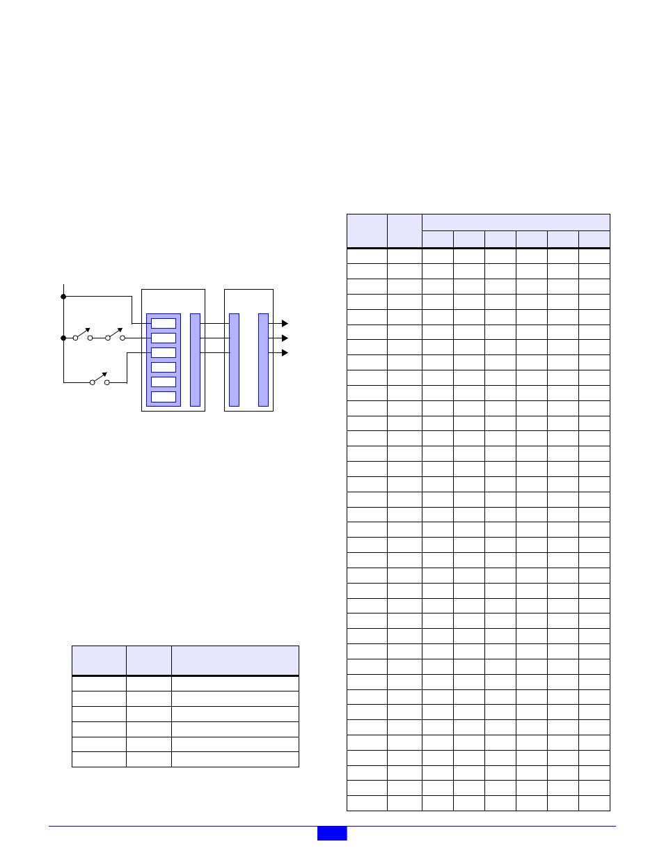
7.2.3 DIO Power Selection Shunt
Each DIO channel may be independently operated from any of
the six external power sources (that are connected to P1 and
P2) by installing the appropriate programming shunt on the
module.
A shunt receptacle matrix is provided for each channel. Each
matrix has six shunt positions, corresponding to the six
external power sources. As shown in Table 17, a programming
shunt must be installed at the position corresponding to the
DIO channel’s desired supply voltage. Only one shunt should
be installed per block.
Each channel’s shunt receptacle matrix is located to the rear of
that channel’s I/O connector.
7.2.4 I/O Connectors
The DIO module employs 48 RJ-12 modular jacks for direct
connection to field wiring, designated J1 to J48.
As shown in Table 18, each jack has five signal circuits: the
shunt-selected interlock power source (PWR) on pin 2,
common ground (GND) on pin 6, and three contiguous DIO
channels (except J24 and J48, which have a reduced number of
DIO channel connections) on pins 3, 4 and 5. Pin signals
labeled “NC” are not connected to any circuitry on the module.
Table 17: Interlock Power Programming Matrix
PWB
Label
Shunt
Pins
Selected Power Source
+24V
1-2
+24V power, always on.
0
3-4
Optional positive DC power #0.
1
5-6
Optional positive DC power #1.
2
7-8
Optional positive DC power #2.
3
9-10
Optional positive DC power #3.
4
11-12
Optional positive DC power #4.
PWR4
PWR3
PWR2
PWR1
PWR0
+24V
2601 MM
TBLK
@J22
P1
P1
P2
2610 DIO
To
Other
IOMs
+24V
ESTOP
SW1
ESTOP
SW2
HOOD
INTERLOCK
Table 18: Pinouts of the I/O Connectors
PWB
Label
RJ-12
Jack
Pin Signal
1
2
3
4
5
6
CH0
J1
NC
PWR
CH0
CH1
CH2
GND
CH1
J25
NC
PWR
CH1
CH2
CH3
GND
CH2
J2
NC
PWR
CH2
CH3
CH4
GND
CH3
J26
NC
PWR
CH3
CH4
CH5
GND
CH4
J3
NC
PWR
CH4
CH5
CH6
GND
CH5
J27
NC
PWR
CH5
CH6
CH7
GND
CH6
J4
NC
PWR
CH6
CH7
CH8
GND
CH7
J28
NC
PWR
CH7
CH8
CH9
GND
CH8
J5
NC
PWR
CH8
CH9
CH10
GND
CH9
J29
NC
PWR
CH9
CH10
CH11
GND
CH10
J6
NC
PWR
CH10
CH11
CH12
GND
CH11
J30
NC
PWR
CH11
CH12
CH13
GND
CH12
J7
NC
PWR
CH12
CH13
CH14
GND
CH13
J31
NC
PWR
CH13
CH14
CH15
GND
CH14
J8
NC
PWR
CH14
CH15
CH16
GND
CH15
J32
NC
PWR
CH15
CH16
CH17
GND
CH16
J9
NC
PWR
CH16
CH17
CH18
GND
CH17
J33
NC
PWR
CH17
CH18
CH19
GND
CH18
J10
NC
PWR
CH18
CH19
CH20
GND
CH19
J34
NC
PWR
CH19
CH20
CH21
GND
CH20
J11
NC
PWR
CH20
CH21
CH22
GND
CH21
J35
NC
PWR
CH21
CH22
CH23
GND
CH22
J12
NC
PWR
CH22
CH23
CH24
GND
CH23
J36
NC
PWR
CH23
CH24
CH25
GND
CH24
J13
NC
PWR
CH24
CH25
CH26
GND
CH25
J37
NC
PWR
CH25
CH26
CH27
GND
CH26
J14
NC
PWR
CH26
CH27
CH28
GND
CH27
J38
NC
PWR
CH27
CH28
CH29
GND
CH28
J15
NC
PWR
CH28
CH29
CH30
GND
CH29
J39
NC
PWR
CH29
CH30
CH31
GND
CH30
J16
NC
PWR
CH30
CH31
CH32
GND
CH31
J40
NC
PWR
CH31
CH32
CH33
GND
CH32
J17
NC
PWR
CH32
CH33
CH34
GND
CH33
J41
NC
PWR
CH33
CH34
CH35
GND
CH34
J18
NC
PWR
CH34
CH35
CH36
GND
CH35
J42
NC
PWR
CH35
CH36
CH37
GND
CH36
J19
NC
PWR
CH36
CH37
CH38
GND