Sensoray 2600 User Manual
Page 57
2600 Family Instruction Manual
52
Chapter 9 : Model 2620 Counter Module
Unlike most other IOM types in the 2600 family, nearly all of
the 2620-specific actions employ a special opcode format that
designates the counter channel to which the action applies.
The opcode byte that is issued to the 2620 is formed by adding
the counter channel number, multiplied by sixteen, to a base
opcode. For example, opcode 0x31 would be used to apply a
SetMode action (base opcode 0x01) to counter channel 3.
Note: Model 2620 has a maximum MRsp size of twenty bytes.
9.4.1 SetMode
Function
Programs a counter channel’s operating mode.
Opcode
0x00 + Chan * 16
Command
(Mode<7:0>),(Mode<15:8>)
Mode
is a 16-bit value, passed LSB first, that is
composed of bit fields that specify the functional
attributes of the counter channel.
Figure 45: Counter Mode MSB
RUN: Enable channel operations.
0 - (default upon module reset) Halt channel,
force core to zero (including bit 32), force
status bits to their default states, reset trigger
latches. Preload and latch registers are not
modified. After writing to the mode register
with this bit cleared, it is necessary to write
to it again with this bit set to start the channel
running.
1 - Run or continue to run in the specified
mode.
OM: Output pin’s mode (2-bit field):
0 - Counter bit 31.
1 - Counter bit 32 (toggles at zero counts).
2 - Active when counts are zero.
3 - Active during counter under/overflow.
XP: Index input polarity:
0 - Active high.
1 - Active low.
PL: Preload trigger (2-bit field):
0 - Preload on soft trigger only.
1 - Preload on index leading edge or soft
trigger.
2 - Preload on zero counts reached or soft
trigger.
3 - Reserved.
LAT: Latch trigger:
0 - Latch on soft trigger only.
1 - Latch on index leading edge or soft trigger.
CET: Count enable trigger:
0 - Enable upon configuration (no trig needed).
1 - Enable on index leading edge.
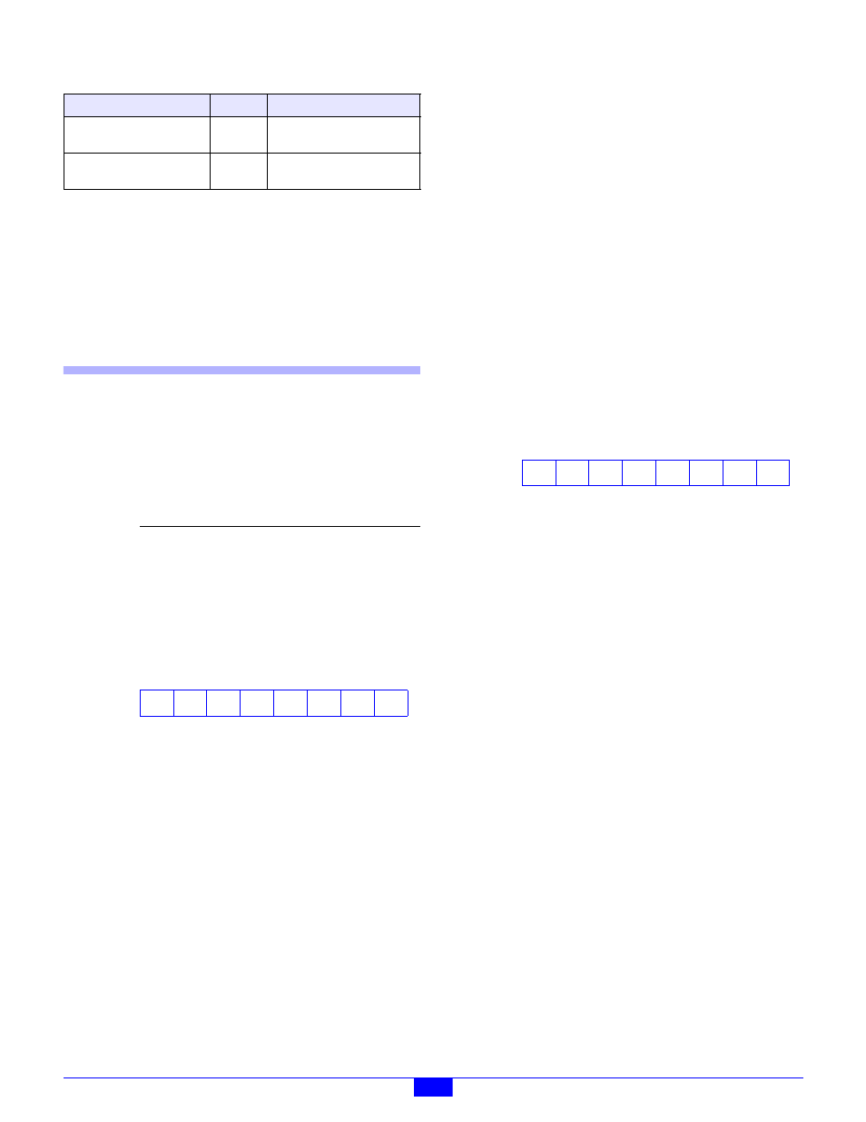
Figure 46: Counter Mode LSB
OP: Output pin’s polarity:
0 - Active high.
1 - Active low.
M: Mode (3-bit field). Modes 0-3 use
quadrature-encoded two-phase clock, modes 4-6
use single-phase clock, and mode 7 uses the
internal clock:
0 - quad x1, clock on rising A.
1 - quad x1, clock on falling A.
2 - quad x2, clock on either edge of A.
3 - quad x4, clock on either edge of A or B.
4 - mono, clock on rising A, B controls count
direction.
5 - mono, clock on falling A, B controls count
direction.
6 - mono, clock on either edge A, B controls
count direction.
7 - internal clock (10MHz), A is the gate
(enables counting while asserted), B controls
count direction.
CD: Count disable trigger:
0 - Never disabled by any trigger.
1 - Disable on index trailing edge (if enabled).
2 - Disable when zero counts reached.
PLM: Select preload register:
0 - Only preload register 0.
1 - Use both preload registers.
GetCountsTs
0x06
Return the channel’s count
with time stamp.
SetCommonControl
0x0F
Program the common
control register.
Parameter
Function
Mode
Collection of bit fields that specify the
counter’s functional attributes.
Table 27: Summary of 2620 Module Actions - Base Opcodes
Command
Opcode
Function
15
RUN
14
OM1
13
OM0
12
XP
11
PL1
10
PL0
9
LAT
8
CET
7
OP
6
M2
5
M1
4
M0
3
CD1
2
CD0
1
PLM
0
XC