4 reset, 5 status flags, 6 actions – Sensoray 2600 User Manual
Page 44
2600 Family Instruction Manual
39
Chapter 7 : Model 2610 Digital I/O Module
7.3.5 Input Debounce
All 48 DIO channel physical states are sampled every 10
milliseconds. The on-board microcontroller applies a
debounce filter to the sampled states, resulting in a 10
millisecond debounce period.
When acquiring physical channel states from the DIO module,
the client always receives the debounced image of the physical
states, which is delayed 10 milliseconds by the debounce
function.
7.4 Reset
Upon module reset, all DIO drivers default to the inactive state
and channels 0 to 23 default to the Standard operating mode.
A DIO module will experience a module reset in response to
any of the following conditions:
• Module power-up.
• Watchdog time-out due to soft or hard fault.
• SoftReset or HardReset action request from the client.
• Communication time-out, which will occur if the client
fails to communicate with the DIO module within a
programmable communication watchdog interval.
7.5 Status Flags
In addition to the standard flag bits that are common to all
IOMs (see Section 3.4.1), the status byte returned by a DIO
module includes one fault flag that is specific to DIO modules
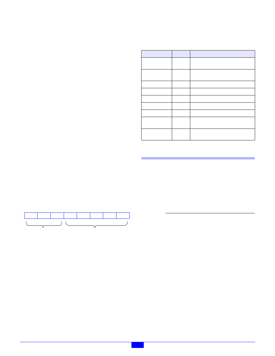
only. The DIO status byte is structured as shown in Figure 37.
Figure 37: DIO Status Byte
STRM
- Active-high bit flag that indicates an error was detected
in the serial data stream that is used to control the DIO output
drivers. This flag can be cleared by invoking a ResetFlags
action.
7.6 Actions
This section describes the programmable actions that are
supported exclusively by the DIO module. These actions may
be employed, in any sequence or combination, in MCmd action
lists.
DIO modules support all of the common actions that are
universally recognized by all IOMs, such as HardReset,
SoftReset
, etc. Refer to Chapter 5 for details.
Note: Model 2610 has a maximum MRsp size of ten bytes.
7.6.1 SetModes
Function
Programs the operating modes for DIO channels
0 through 7.
Opcode
0x00
Command (ModeFlags)
Response
none
Notes
Each of channels 0 through 7 may operate in
either the Standard mode or the PWM mode.
Following a reset, all channels default to the
Standard operating mode.
When a channel’s operating mode is first
changed to the PWM mode, its output driver duty
cycle is reset to zero; this prevents the output
from going active until the duty cycle is explicitly
set by a SetPwmRatio action.
7
RST
6
CERR
5
4
HRST
3
0
2
1
0
0
0
DIO-specific
Standard
STRM
0
Table 19: Summary of DIO Module Actions
Command
Opcode
Function
SetModes
0x00
Set operating modes for DIO channels
0-7.
GetModes
0x01
Return operating modes for DIO
channels 0-7.
SetPwmRatio
0x02
Program PWM duty cycle and period.
GetPwmRatio
0x03
Return PWM duty cycle and period.
GetInputs
0x04
Return all DIO input states.
GetOutputs
0x05
Return all DIO output states.
SetOutputs
0x06
Program all DIO output states.
SetModes32
0x07
Set operating modes for DIO channels
0-31 (Vers. 1.02 or higher).
GetModes32
0x08
Return operating modes for DIO
channels 0-31 (Vers. 1.02 or higher).
Parameter
Function
ModeFlags
Operating modes for channels 0 to 7.
Each bit is associated with a channel
number. For example, bit 4 is
associated with channel 4. Set a bit
to one to select the PWM mode, or to
zero to select the Standard mode.