2 remote sense shunts, 3 field wiring connectors – Sensoray 2600 User Manual
Page 50
2600 Family Instruction Manual
45
Chapter 8 : Model 2612 Strain Gauge/RTD Module
Install a shunt on the IPB at pins 3-4 to enable the bridge
completion network and connect the divider output to Input-.
In this case, the voltage on Input+ must be in the range
between Ref+ and Ref-.
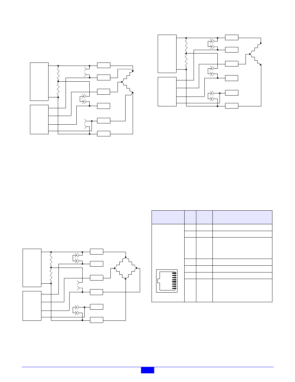
Figure 40: Half-bridge Device With Internal Bridge Completion
Half-bridge strain gauges, as well as RTDs and thermistors,
may be connected as shown in Figure 40 to implement remote
excitation sensing. Of the two external resistors shown here,
the bottom one is the sensor element and the top one is a fixed,
low tempco resistor.
8.5.2 Remote Sense Shunts
Each channel must be configured for either local or remote
excitation sensing. Remote sensing (Figure 39 and Figure 40)
makes it possible to compensate voltage drop on the excitation
supply wires. If this drop is not a concern, local sensing may be
used.
To enable local sensing, install a shunt on the channel’s IPB at
pins 1-2 (positive) and pins 5-6 (negative). When local sensing
is employed, there should be no connections to the Ref pins.
Figure 41: Full-bridge Device With Local Sensing
Figure 42: Half-bridge Device With Local Sensing
Half-bridge strain gauges, as well as RTDs and thermistors,
may be connected as shown in Figure 42 if remote sensing is
not needed. Of the two external resistors shown here, the
bottom one is the sensor element and the top one is a fixed, low
tempco resistor.
8.5.3 Field Wiring Connectors
Each channel has two dedicated, eight-pin connectors for field
wiring: an RJ-45 socket and a pluggable terminal block.
Connectors are labeled “CH0” through “CH3.” The connector
pinout is identical for all channels. Either of a channel’s two
connectors may be used, as best fits the system requirements.
8.5.3.1 RJ-45 Connectors
8.5.3.2 Terminal Blocks
Pin 1 of a TB may be physically located by orienting the board
so that the TB’s silkscreen label reads from left to right; pin 1
Power+
Ref+
Input+
Input-
Ref-
Power-
P
o
w
e
r
A
D
C
1
2
3
4
6
5
Power+
Ref+
Input+
Input-
Ref-
Power-
P
o
w
er
A
D
C
1
2
3
4
6
5
Table 22: Pinouts of RJ-45 Channel Connectors
Layout
(top view)
Pin
Name
Function
1
Power-
Negative excitation output.
2
Power+
Positive excitation output.
3,6
Shld
This may be connected to a cable
shield, but the shield conductor must
be unconnected at the remote end of
the cable to avoid ground loops.
4
In+
Positive signal input.
5
In-
Negative signal input.
7
Vref-
Negative reference input.
8
Vref+
Positive reference input.
Power+
Ref+
Input+
Input-
Ref-
Power-
P
o
w
er
A
D
C
1
2
3
4
6
5
8
1