3 channel operating modes, 1 input operation, 2 standard output operation – Sensoray 2600 User Manual
Page 43: 3 wired-or operation, 4 output modes
2600 Family Instruction Manual
38
Chapter 7 : Model 2610 Digital I/O Module
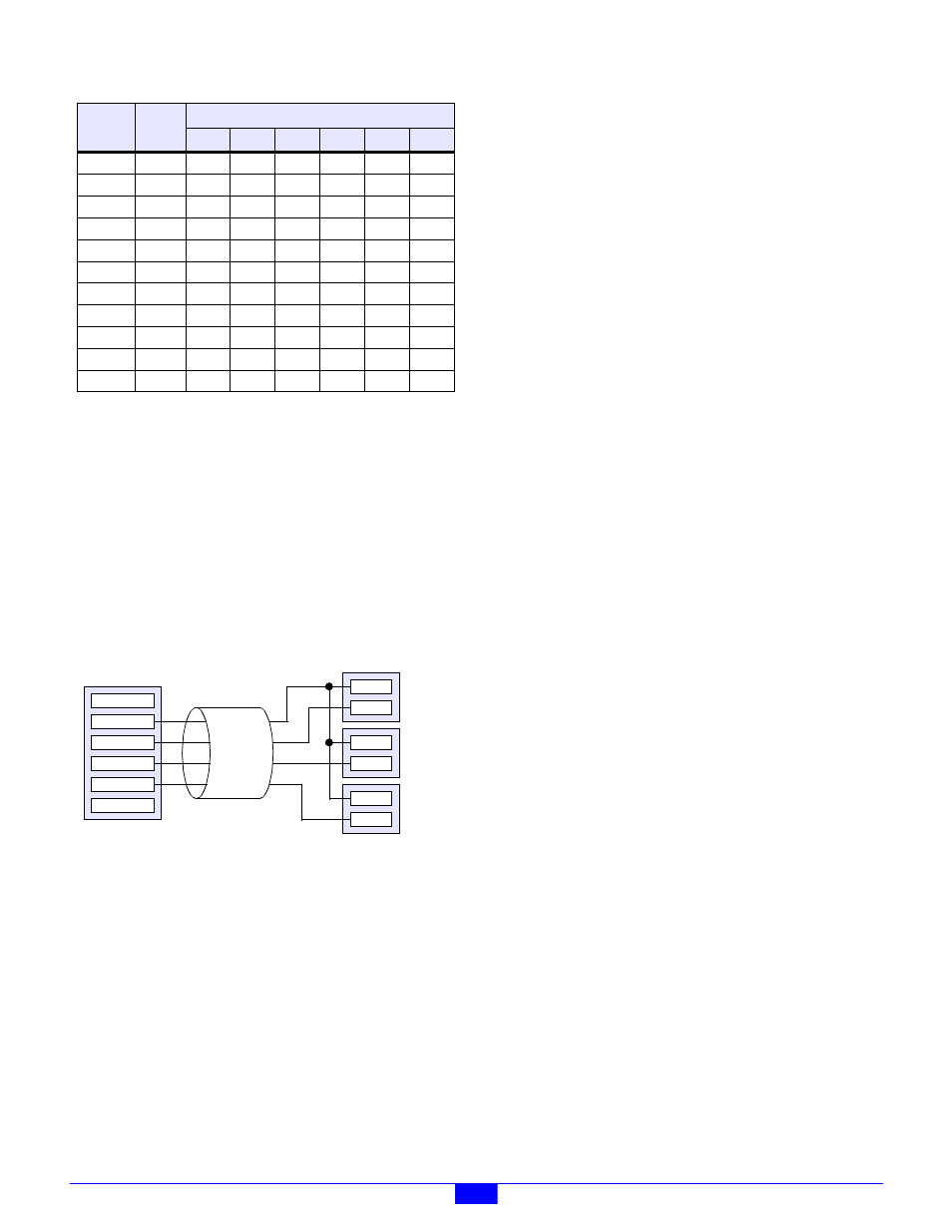
Except for J24 and J48 (channels 46 and 47), each jack exposes
connections to three DIO channels. For example, J1 provides
connections to channels 0, 1 and 2. This feature can simplify
wiring in cases where a single field cable must carry more than
one DIO signal.
To get an idea of how this feature might be used, consider the
case of a three-lamp lintern assembly with integrated cable
(Figure 36). The source end of the cable can terminate to a
single jack on the DIO module, which in turn provides access
to all three lamp control signals.
Figure 36: Multiple Channels on Each I/O Jack
7.2.4.1 Restrictions
There are a few restrictions related to connecting multiple DIO
channels through a single RJ-12 jack:
1. When multiple DIO channels connect to field wiring
through a single jack, the channels that share the jack need
not be powered from the same power source, but only one
power source per jack is available to the field wiring.
An example of this can be seen in Figure 36, in which all
three lamps are powered from a common PWR source;
this would not be possible if the lamps required differing
supply voltages, because only one supply voltage is
available from the jack.
2. If power can be interrupted on a DIO channel, the channel
must connect to field wiring through a dedicated jack that
is not shared by any other channels.
For example, suppose PWR3 may be interrupted by an
interlock contact, and channel 42 is powered from PWR3.
In this case, the jack that connects field wiring to channel
42 (e.g., J21, J22 or J40) may connect to CH42, GND and
PWR
, but it must not make field wiring connections to any
other DIO channels.
7.3 Channel Operating Modes
Each channel may be independently operated as an input or a
programmed, standard output.
7.3.1 Input Operation
To use a channel as an input, the client must ensure that it
never programs the channel to its active state. Since the client
never enables the channel’s output driver, the channel may be
driven by an external, active-low driver. When the external
driver is not driving the channel low, the channel’s pull-up
resistor will force the channel to its inactive state.
7.3.2 Standard Output Operation
When a channel is used as a standard output, the client simply
programs the channel’s output driver to the desired state. The
channel is either driven low by the channel’s on-board driver,
or it is pulled high by the channel’s pull-up resistor.
7.3.3 Wired-or Operation
Since a DIO channel’s output driver is open-collector, it is
possible to “wire-or” a channel by operating it both as a
programmed output and by connecting the channel to one or
more external open-collector drivers. If any of the connected
drivers asserts its active-low output, the channel will be driven
to its active state.
7.3.4 Output Modes
DIO channels 0 to 23 are unique in that they support two
different output modes: Standard and PWM. In the Standard
mode, a channel may be driven as described earlier: either by
its explicitly programmed onboard driver or by an external
current sink. In the PWM mode, the channel’s output driver is
cycled on and off at a client-specified duty cycle.
The output mode may be independently configured for each
channel. For example, channel 0 can operate in the PWM
mode while channels 1 to 23 operate in the Standard output
mode.
All channels support the Standard operating mode, which is the
default mode following a reset. Only channels 0 through 31
may be configured for the PWM mode; channels 32 through 47
support only the Standard mode.
CH37
J43
NC
PWR
CH37
CH38
CH39
GND
CH38
J20
NC
PWR
CH38
CH39
CH40
GND
CH39
J44
NC
PWR
CH39
CH40
CH41
GND
CH40
J21
NC
PWR
CH40
CH41
CH42
GND
CH41
J45
NC
PWR
CH41
CH42
CH43
GND
CH42
J22
NC
PWR
CH42
CH43
CH44
GND
CH43
J46
NC
PWR
CH43
CH44
CH45
GND
CH44
J23
NC
PWR
CH44
CH45
CH46
GND
CH45
J47
NC
PWR
CH45
CH46
CH47
GND
CH46
J24
NC
PWR
CH46
CH47
NC
GND
CH47
J48
NC
PWR
CH47
NC
NC
GND
Table 18: Pinouts of the I/O Connectors
PWB
Label
RJ-12
Jack
Pin Signal
1
2
3
4
5
6
1:NC
2:PWR
3:CHx
4:CHx+1
5:CHx+2
6:GND
RJ-12 Jack
on 2610
PWR+
PWR-
Yellow
PWR+
PWR-
Green
PWR+
PWR-
Red
Lamp Column
Field
Wiring