3 relay power selection shunt, 4 i/o connectors – Sensoray 2600 User Manual
Page 75
2600 Family Instruction Manual
70
Chapter 12 : Model 2653 SSR Module
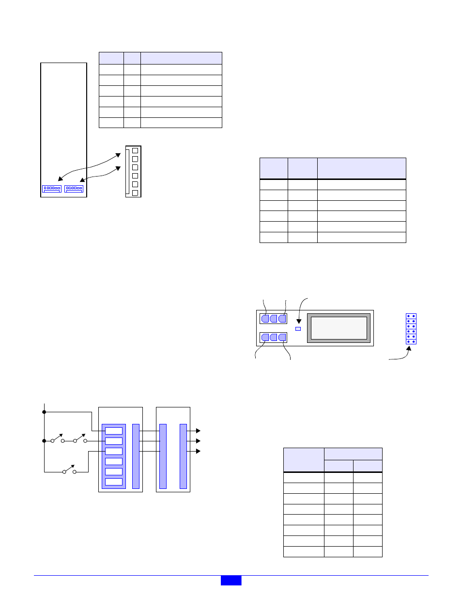
Figure 63: Pinouts of Connectors P33 and P34
The external DC power sources need not be derived from
interlock contacts, but by employing interlocked power
sources, the system interlock cabling can be minimized. This
feature is especially useful for guaranteeing the fail-safe
shutdown of select SSR channels in the event of a critical
condition such as emergency stop (ESTOP) activation, open
safety hood, etc.
Figure 64 illustrates a system in which PWR0 is connected to
multiple system emergency stop contacts, and PWR1 is routed
through a safety hood interlock contact. Note that all of the
external power sources are daisy-chained from module to
module. Any SSR that is configured to use PWR0 will
automatically lose power when either ESTOP contact is
opened, and any SSR that is configured to use PWR1 will lose
power when the hood opens. All other SSRs use the +24V
“always on” power source and thus are unaffected by interlock
contacts. PWR2, PWR3 and PWR4 are not used in this
application.
Figure 64: Wiring Example With Interlock Contacts
Use Sensoray cable assembly, part number 2600C1, to connect
P1 or P2 to the power daisy chain
12.2.3 Relay Power Selection Shunt
Each relay channel may be independently operated from any of
the six external DC power sources (that are connected to P33
and P34) by installing the appropriate programming shunt.
A shunt receptacle matrix is provided for each channel. Each
matrix has six shunt positions, corresponding to the six
external DC power sources. As shown in Table 38, a 2mm
programming shunt (supplied with the 2653) must be installed
at the position corresponding to the relay channel’s target
power source. Only one shunt should be installed per matrix.
Each channel’s shunt receptacle matrix is located adjacent to
its SSR socket as shown in Figure 65.
Figure 65: SSR Channel Layout (top view)
12.2.4 I/O Connectors
The 2653 module employs thirty two connectors for field
wiring. Each channel uses one connector for line and one for
load (see Figure 65).
2653
P34
6 - PWR4
5 - PWR3
4 - PWR2
2 - PWR0
1 - +24V
3 - PWR1
Name Pin
Function
+24V
1
+24V power, always on.
PWR0
2
Optional positive DC power #0.
PWR1
3
Optional positive DC power #1.
PWR2
4
Optional positive DC power #2.
PWR3
5
Optional positive DC power #3.
PWR4
6
Optional positive DC power #4.
(top view)
P33
PWR4
PWR3
PWR2
PWR1
PWR0
+24V
2601 MM
TBLK
@J22
P1
P33
P34
2653 SSR
To
Other
IOMs
+24V
ESTOP
SW1
ESTOP
SW2
HOOD
INTERLOCK
Table 38: Interlock Power Programming Matrix
PWB
Label
Shunt
Pins
Selected Power Source
+24V
1-2
+24V power, always on (default)
0
3-4
Optional positive DC power #0.
1
5-6
Optional positive DC power #1.
2
7-8
Optional positive DC power #2.
3
9-10
Optional positive DC power #3.
4
11-12
Optional positive DC power #4.
Table 39: Line and Load Connectors
Relay
Channel
Connector
Line
Load
CH0
P2
P1
CH1
P4
P3
CH2
P6
P5
CH3
P8
P7
CH4
P10
P9
CH5
P12
P11
CH6
P14
P13
CH7
P16
P15
SSR
12
10
8
6
4
2
11
9
7
5
3
1
+24V-
PWR0-
PWR1-
PWR2-
PWR3-
PWR4-
Indicator lights when relay is energized
Line+
Line
Load
Line-
Load-
Load+
Power Programming Matrix