6 reset, 7 actions, 1 setmode – Sensoray 2600 User Manual
Page 51: 2 getinputs
2600 Family Instruction Manual
46
Chapter 8 : Model 2612 Strain Gauge/RTD Module
is the left-most pin on the TB. TB pins are numbered in
sequential order, beginning with pin 1.
8.6 Reset
Upon module reset, all power outputs switch to 1.25 volts out.
A 2612 module will experience a module reset in response to
any of the following conditions:
• Module power-up.
• Watchdog time-out due to soft or hard fault.
• SoftReset or HardReset action request from the client.
• Communication time-out, which will occur if the client
fails to communicate with the 2612 module within a
programmable communication watchdog interval.
8.7 Actions
This section describes the programmable actions that are
supported exclusively by 2612 modules. These actions may be
employed, in any sequence or combination, in MCmd action
lists. In addition to the actions listed here, the 2612 module
also supports all of the common actions that are universally
supported by all IOMs.
Note: Model 2612 has a maximum MRsp size of 26 bytes.
8.7.1 SetMode
Function
Programs the conversion mode of one analog
input channel.
Opcode
0x00
Command (Chan),(Mode<7:0>),(Mode<15:8>),
(Mode<23:16>),(Mode<31:24>)
Mode:
bits 31 to 20 specify the oversample ratio
(OSR), as shown in the following table. See
Section 8.2.1 for details. Bit 19 specifies the
speed multiplier mode. Bits 18 to 0 must be set to
zero.
Response
none
8.7.2 GetInputs
Function
Returns the digitized values of all analog input
channels.
Opcode
0x01
Command none
Response
(s[0][0]),(s[0][1]),
(s[0][2]),(s[0][3]),
(s[1][0]),(s[1][1]),
(s[1][2]),(s[1][3]),
(s[2][0]),(s[2][1]),
(s[2][2]),(s[2][3]),
(s[3][0]),(s[3][1]),
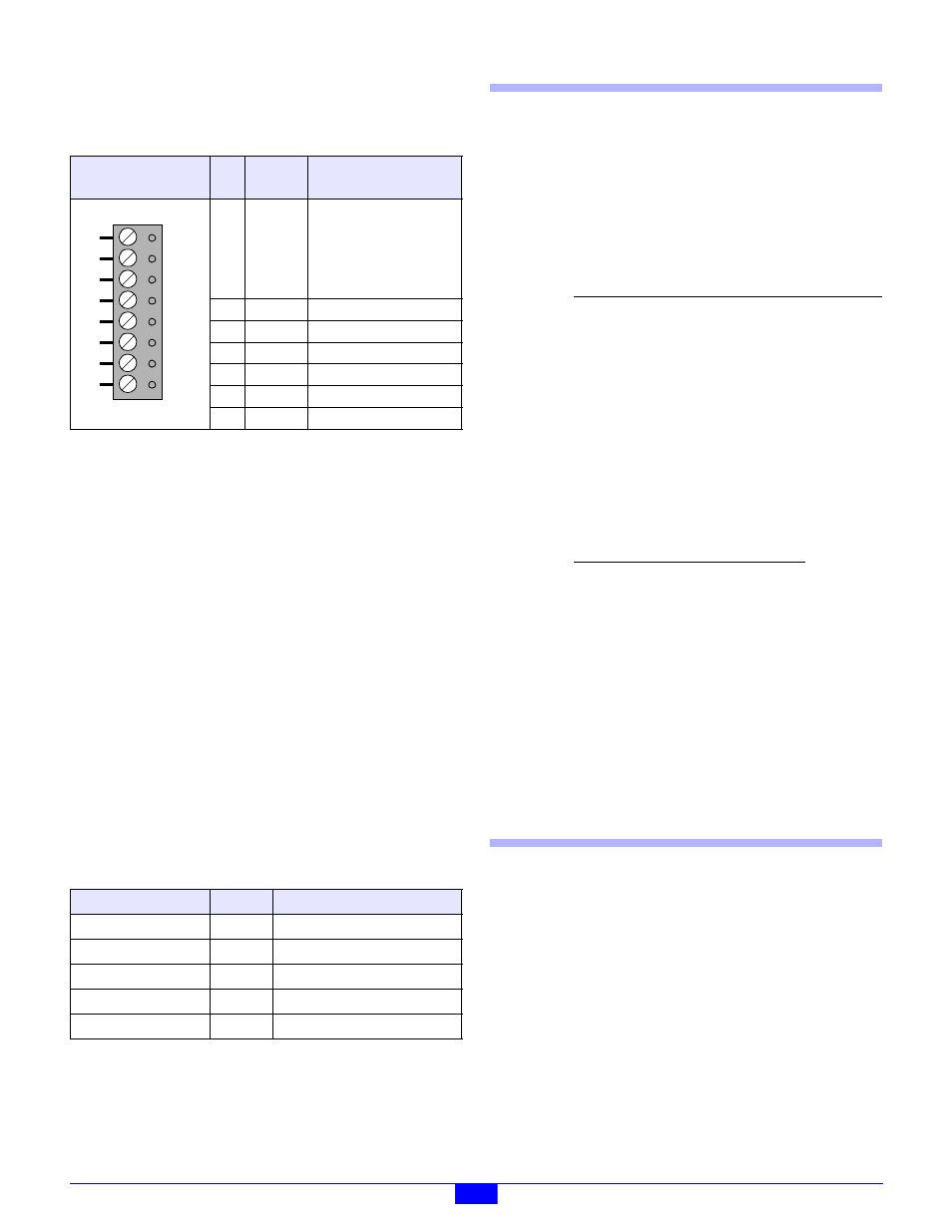
Table 23: Pinouts of Channel Terminal Blocks
Layout
(top view)
Pin
Name
Function
1,8
Shld
This may be connected to a
cable shield, but the shield
conductor must be
unconnected at the remote
end of the cable in order to
avoid ground loops.
2
Power+
Positive power output.
3
Vref-
Negative reference input.
4
In+
Positive signal input.
5
In-
Negative signal input.
6
Vref+
Positive reference input.
7
Power-
Negative power output.
Table 24: Summary of Model 2612 Actions
Command
Opcode
Function
SetMode
0x00
Program input mode.
GetInputs
0x01
Return ADC values.
SetVoltages
0x02
Select output voltages.
ReadEeprom
0x0D
Return data from EEPROM
WriteEeprom
0x0E
Write data to EEPROM
1
2
3
4
5
6
7
8
Parameter
Function
Chan
Analog output channel to be
programmed. Values may range from 0
to 3, inclusive. The six high-order bits
are reserved and should be set to zero.
Mode
32-bit value that specifies the
conversion mode for the target channel.
Value
OSR
0xA01
64
0xA02
128
0xA03
256
0xA04
512
0xA05
1024
0xA06
2048
0xA07
4096
0xA08
8192
0xA09
16384
0xA0F
32768