4 hardware configuration – Sensoray 2600 User Manual
Page 35
2600 Family Instruction Manual
30
Chapter 6 : Model 2608 Analog I/O Module
6.3.1.1 Returned Data
In the case of the 16 external input channels, both the snapshot
and integrated values may be accessed by the client. Snapshot
values are most useful if minimum data age is required, while
integrated values provide superior noise reduction and line
frequency rejection.
Only integrated values are available from the on-board
temperature sensor and reference standards channels. This is
because these values are not intended for use by real-time
applications.
Although the snapshot and integrated values may be directly
accessed by a client, it is usually preferable to use the
middleware data acquisition functions supplied on the
distribution media; these functions perform offset and gain
corrections, return acquired voltages in engineering units and
provide extensive support for thermocouples.
6.3.2 Thermocouples
Onboard temperature sensors are mounted near the analog
input terminations to provide reference junction compensation
for thermocouples (TCs). These sensors occupy dedicated
input channels so that all of the application channels will
remain available for external signal measurements.
When interfaced to a TC, an AIN channel must be configured
for the ±100mV input range. This provides sufficient gain for
resolving the TC signal, and it is the input range that is
expected by the distribution media, which translates TC
voltage into temperature units. Refer to the documentation
supplied with the distribution media for information about TC
software support.
The TC’s common mode voltage (CMV) must not exceed the
maximum specified CMV limits of the 2608 AIN channels. To
prevent excessive CMV, the TC should have no electrical
connection at its hot end (i.e., it should be an “isolated” TC)
and hardware programming shunts should be installed as
described in Section 6.4.2.1.
6.3.3 4-20 mA Current Loops
An AIN channel must be configured for the ±10V input range
when it will be used to measure a 4-20 mA current loop; this is
the input range that is expected by the middleware, which
translates the measured loop current into engineering units.
Refer to the documentation supplied with the distribution
media for details.
To guarantee conformance to the maximum AIN common
mode voltage specification, only the grounded end of the
current loop should be connected to the AIN channel.
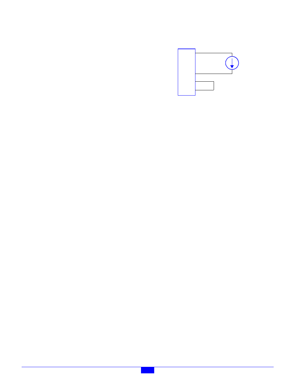
The AIN channel may be configured to provide excitation for
current loops, as shown in the following schematic. Note that
in this case, the loop current power is provided directly by the
AIN channel; see Section 6.4.2.2 for an explanation of how to
configure option shunts so that the AIN channel will provide
power for a current loop.
Figure 33: Typical Current Loop Schematic
6.4 Hardware Configuration
6.4.1 Analog Outputs
Each AOUT channel is provided with a 6-pin header—called
the output programming block, or OPB—that is designed to
accept hardware programming shunts. Various configuration
options are programmed by installing shunts in the appropriate
positions on the OPB, as described in the following sections.
6.4.1.1 Remote Sense Shunts
AOUT channels must be individually configured for either
local or remote output sensing.
Many control systems generate control outputs based on
process feedback. Local sensing is well suited for such
applications, as the absolute accuracy of the control signal is
not a concern. To enable local sensing, install a shunt on the
AOUT channel’s OPB at pins 1-2. When local sensing is
employed, there should be no connection to the Sense pin on
the AOUT channel’s connector.
Remote sensing should be used if high output voltage accuracy
is required in the presence of widely varying or large load
currents. Remote sensing requires two conductors for the
output’s high side signal: one to supply load current and
another to sense the applied voltage at the load. If remote
sensing is employed, make sure to remove the shunt (if there is
one) on the AOUT channel’s OPB at pins 1-2.
6.4.1.2 Power Distribution Shunts
It is sometimes necessary to supply additional operating power
to devices that are connected to AOUT channels. The OPB
may be programmed to route either +24V or +10V to an
external device via the associated AOUT connector. The
selected voltage is routed to the connector on pin 5.
Install a shunt on the OPB at pins 3-4 to route 24VDC to the
connector. Install a shunt on the OPB at pins 4-6 to route
10VDC to the connector.
6.4.1.3 Connectors
Each AOUT channel is provided with a dedicated, five-pin
connector. The connectors are labeled “AOUT0” through
PH
SENSOR
SH
+24V
SL
PL
0V
AIN
Terminal
Block