Sensoray 2600 User Manual
Page 27
2600 Family Instruction Manual
22
Chapter 4 : Serial Communication Server
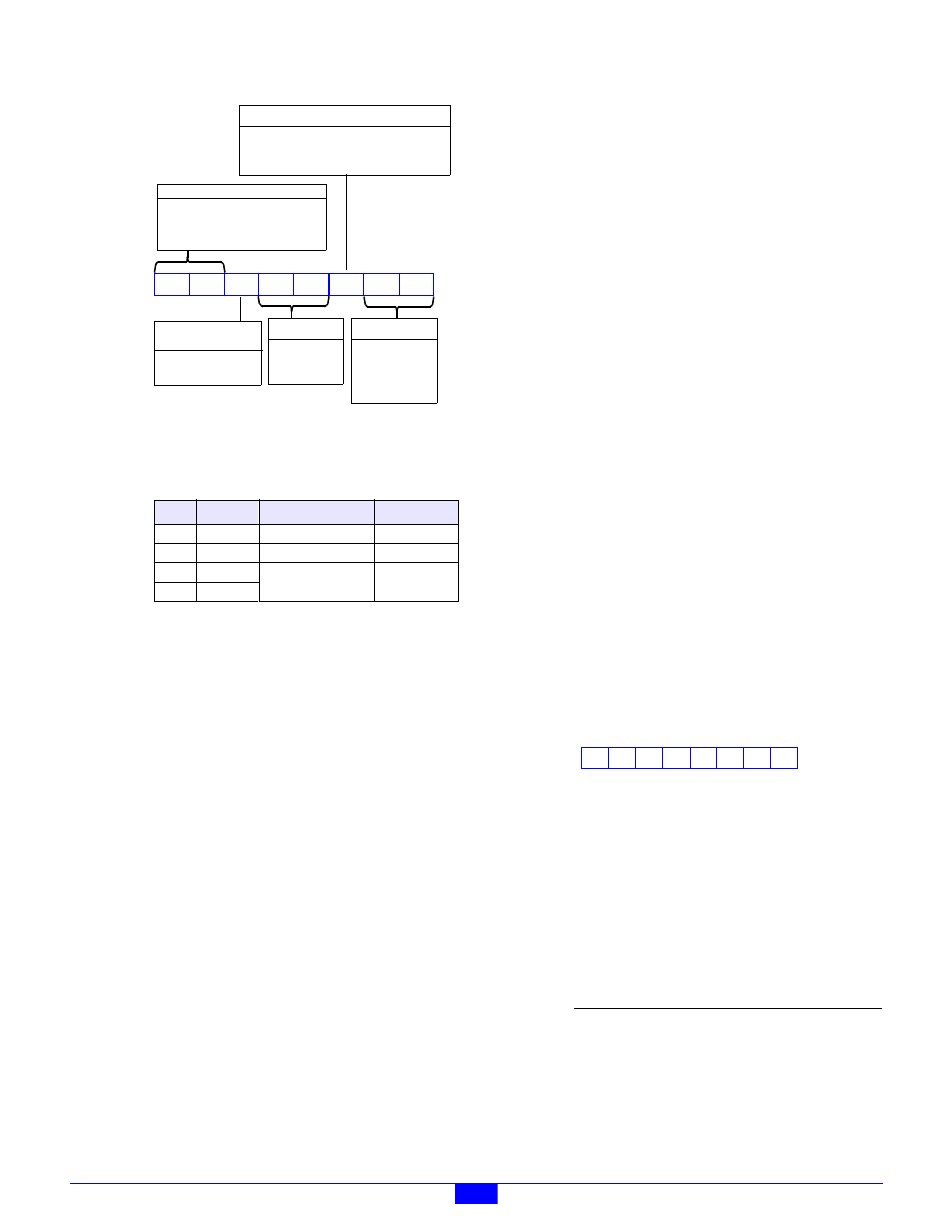
Figure 30: Attributes Byte
PHY
These two bits specify the physical layer type and
behavior as follows:
Notes
1. PHY values 10 and 11 are available only on model 2601
Revision D (or later) circuit boards.
PHY=00
: Full-duplex RS-232.
PHY=01
: Full-duplex RS-422. Both receiver
and transmit line driver are enabled at all times.
PHY=10
: Half-duplex RS-422 or RS-485. The
transmit line driver is enabled only while
characters are being sent; it is automatically
disabled (tri-stated) when the transmitter is idle.
The receiver is enabled only when the transmitter
is idle, so that receive characters are blocked
while the transmitter is active. The receiver
turn-around time is 250 microseconds,
maximum.
PHY=11
: Full-duplex RS-422 or RS-485. The
transmit line driver is enabled only while
characters are being sent; it is automatically
disabled (tri-stated) when the transmitter is idle.
The receiver is enabled at all times. This mode
can be useful for multi-master RS-485 device
networks that require collision detection. The
receiver turn-around time is 250 microseconds,
maximum.
Refer to Section 4.2.2 for information about how
to configure PHY for various device network
topologies.
FLOW
This bit enables XON/XOFF flow control. See
Section 4.1.1 for information about flow control.
PAR
These two bits specify whether even, odd, or no
parity will be applied to transmitted and received
characters. When even or odd parity is enabled,
all incoming characters are parity checked and
any parity errors will be detected and reported.
STOP
This bit specifies the number of stop bits to send
when transmitting a character.
DAT
These two bits specify the number of data bits to
be used in both transmitted and received
characters.
4.4.1.3 LED Behavior
The LEDs byte is shown in Figure 31. When set
to logic one, each bit will cause the com port’s
status LED to light for approximately 100
milliseconds in response to the associated event.
Any combination of these bits may be specified.
For example, the XMT and RCV bits may both be
set, in which case the LED will light when a
character is sent or received at the com port.
After a module reset, the RCV flag is set and all
other flags are reset to zero.
Figure 31: LEDs Byte
XMT
causes the LED to light when a character is
transmitted.
RCV
causes the LED to light when a character is
received.
ERR
causes the LED to light when a receiver
break condition is detected or when an error
(framing, overrun or parity) is detected.
Response
(Status)
Notes
The target com port must be closed when this
command is issued. If the com port is open, the
command will be rejected and the returned status
byte’s REJ flag will be set.
PHY
Duplex
Type
Tx Enabled
00
Full
RS-232
Always
01
Full
RS-422
Always
10
1
Half
RS-422 / RS-485
When
Sending
11
1
Full
FLOW
PAR0
STOP
DAT1 DAT0
PAR1
00 = 5 bits
Char Size
01 = 6 bits
10 = 7 bits
11 = 8 bits
X0 = None
Parity
01 = Odd
11 = Even
0 = 1 bit
Stop Bit Length (in bit times)
1 = 1.5 bits (char size 5)
1 = 2 bits (char sizes 6,7,8)
XON/XOFF
00 = RS232
Physical Layer
01 = RS422, Tx always on
Flow Control
PHY1 PHY0
10 = RS485
11 = RS422, idle 3-state
0 = Disabled
1 = Enabled
Parameter
Function
Status
Com port status. The REJ bit flag
will be set if the com port is open.
7
0
6
0
5
4
0
3
XMT
2
1
0
RCV ERR
0
0