3 reset, 4 status flags, 5 actions – Sensoray 2600 User Manual
Page 65
2600 Family Instruction Manual
60
Chapter 10 : Model 2650 Relay Module
10.3 Reset
All drivers default to the inactive state (relays coils are all
de-energized) upon module reset. 2650 modules undergo
module reset in response to any of the following conditions:
• Module power-up.
• Reset action requested by the Ethernet client.
• Watchdog time-out due to soft or hardware fault.
• Communication time-out, which will occur if the client
fails to communicate with the 2650 module within a
programmable communication watchdog interval.
10.4 Status Flags
In addition to the standard flag bits that are common to all
IOMs (Section 3.4.1), the returned status byte includes two
fault flags that are specific to 2650 modules only. The status
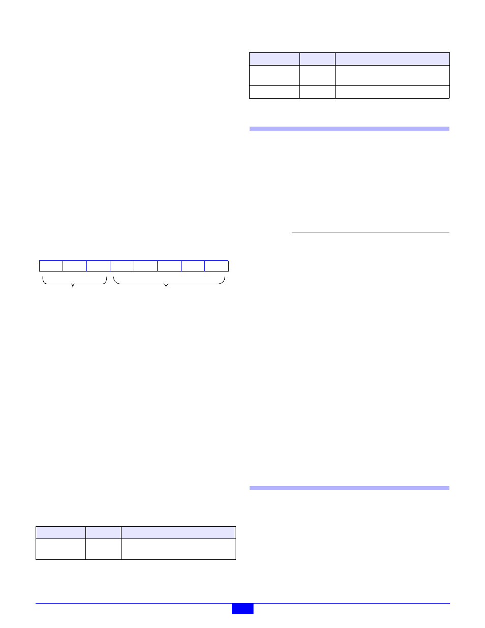
byte is structured as shown in Figure 55.
Figure 55: RLYx Status Byte:
DRVR
- Active-high bit flag that indicates one or more relay
coil drivers failed to go to the commanded state. This may be
caused by a driver fault, a shorted relay coil or a serial data
stream problem.
STRM
- Active-high bit flag that indicates an error was detected
in the serial data stream that is used to control relay drivers and
monitor driver states.
2650-specific fault flag bits can be cleared by invoking a
ResetFlags
action.
10.5 Actions
This section describes the programmable actions that are
supported exclusively by 2650 modules. These actions may be
employed, in any sequence or combination, in MCmd action
lists.
2650 modules support all of the common actions that are
universally recognized by all IOMs, such as HardReset,
SoftReset
, etc. Refer to Chapter 5 for details.
Note: Model 2650 has a maximum MRsp size of eleven bytes.
10.5.1 GetInputs
Function
Returns the physical states of all relay channels.
Opcode
0x00
Command none
Response
(States)
Notes
Each channel includes a monitoring circuit that
enables the on-board processor to determine the
physical state of the relay coil driver. This action
returns the monitored physical state of each coil
driver, even if the relay is not present or its coil
winding has opened.
Coil driver states are acquired periodically at two
millisecond intervals. Consequently, States
may not accurately reflect the state of a coil
driver that has changed its physical state within
the last two milliseconds.
After the coil drivers have been stable for at least
two milliseconds, the States value returned by
GetInputs
should agree with the States
value last programmed by SetOutputs (unless
a module reset has occurred).
10.5.2 GetOutputs
Function
Returns the programmed coil driver states of all
relay channels.
Opcode
0x01
Command none
Table 31: Summary of Relay Module Actions
Command
Opcode
Function
GetInputs
0x00
Return the physical states of all relay
coil drivers.
7
RST
6
CERR
5
4
HRST
3
0
2
1
0
0
0
2650-specific
Standard
DRVR STRM
GetOutputs
0x01
Return the programmed states of all
relay coil drivers.
SetOutputs
0x02
Program all relay coil drivers.
Parameter
Function
States
Bit flags that represent the physical
relay states. Each bit is associated with
one relay channel. For example, bit 7 is
associated with relay channel 7. Any
bit set to one indicates the associated
channel is set to the active state; any bit
set to zero indicates the channel is set to
the inactive state.
Table 31: Summary of Relay Module Actions
Command
Opcode
Function