Connections and indicators, Figure 2.1, Ld1500 connections and indicators – RLE LD1500 V.3.1 User Manual
Page 13: Onnections, Ndicators
rletech.com
LD1500 User Guide
13
C
H A P T E R
C
HAPTER
0
C
ONNECTIONS
AND
I
NDICATORS
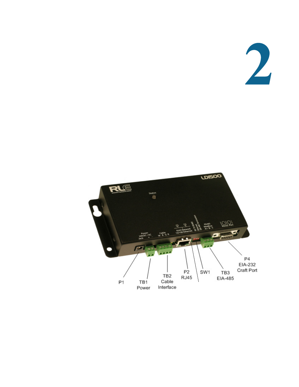
The LD1500 contains one circuit board. All connections are accessible when the unit is inside
of its enclosure. The connectors on the main board, found at the bottom of the following
photograph, are labeled TB1 through TB3 and P1 through P4.
Figure 2.1 LD1500 Connections and Indicators
Status LED
See also other documents in the category RLE Equipment:
- LD2000 Quick Start (2 pages)
- LD300 (2 pages)
- LDZ4 (19 pages)
- LD2000 (78 pages)
- LD5100 Quick Start (2 pages)
- LD310 (2 pages)
- LD5000 Quick Start (4 pages)
- LD1000 (2 pages)
- LD5100 (72 pages)
- 10K Quick Start (2 pages)
- F200 (2 pages)
- LDRA6 Quick Start (2 pages)
- 10K V.2.5.a (44 pages)
- LD1500 Quick Start (2 pages)
- LD5000 (92 pages)
- LD2100 Quick Start (2 pages)
- LD5200 Quick Start (2 pages)
- FDS-Wi Quick Start (2 pages)
- GD100 (26 pages)
- FDS-Wi V.2.5 (74 pages)
- LD2100 V.2.6 (92 pages)
- LD5200 V.2.3 (118 pages)
- F-Series Quick Start (2 pages)
- F110 Quick Start (2 pages)
- Wi-MGR Quick Start (2 pages)
- Wi-MGR V.1.6 (74 pages)
- FMS Quick Start (2 pages)
- FMS32 (92 pages)
- Ground Fault Monitor (2 pages)
- RA1x2 (2 pages)
- Protocol Converter Quick Start (2 pages)
- Protocol Converter V.2.4 (70 pages)
- Falcon EM (146 pages)
- FMS V.1.13 (226 pages)