Packet communications for the seahawk 10k, 1 function 03: read output registers, Function 03: read output registers – RLE 10K V.2.5.a User Manual
Page 31: Table 4.2, Read output register packet structure, Table 4.3, Output registers
rletech.com
SeaHawk 10K User Guide
31
4
Modbus Communication
4.2.
Packet Communications for the SeaHawk 10K
4.2.1 Function 03: Read Output Registers
To read the SeaHawk 10K parameter values, the master must send a Read Output Registers
request packet.
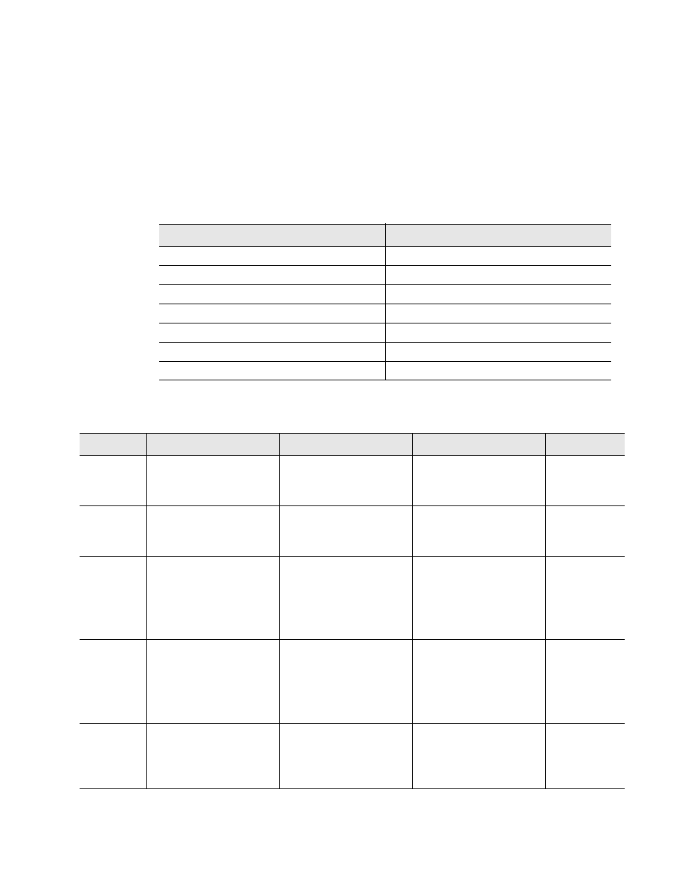
The Read Output Registers request packet specifies a start register and the number of registers
to read. The start register is numbered from zero (40001 = zero, 40002 = one, etc.).
Read Registers Request Packet
Read Registers Response Packet
Slave Address (1 byte)
Slave Address (1 byte)
03 (Function code) (1 byte)
03 (Function code) (1 byte)
Start Register (2 bytes)
Byte count (1 byte)
# of registers to read (2 bytes)
First register (2 bytes)
CRC Checksum (2 bytes)
Second register (2 bytes)
…
Cry Checksum (2 bytes)
Table 4.2
Read Output Register Packet Structure
Register
Name
Description
Units
Range
40001
Leak Threshold
Trip point for leak alarm
25-175 uAmps
Default: 120 uAmps
0-65535
40002
Contamination
Threshold
Trip point for
contamination alarm
25-175 uAmps
Default: 50 uAmps
0-65535
40003
Re-alarm Interval
(read-only)
Amount of time that
passes before unit
resends alarm
notification
Note: Set with DIP SW1;
this register is read-only.
0 (Disabled) or 4 hours
Default: 0 (Disabled)
0-65535
40004
Latched Alarms
(read-only)
Latched alarm requires
SeaHawk 10K to be
reset once alarm is
cleared.
Note: Set with DIP SW1;
this register is read-only.
0 = Disabled
1 = Enabled
Default: Disabled
0-65535
40005
Silence Audible Alarm
Indicates whether or not
the audible alarm sounds
when the SeaHawk 10K
goes into alarm state
0 = Disabled
1 = Enabled
Default: Disabled
0-65535
Table 4.3
Output Registers