2 tb2: leader cable, Tb2: leader cable – RLE 10K V.2.5.a User Manual
Page 16
16
SeaHawk 10K User Guide
800.518.1519
2
Installation and Configuration
2
DIP switches are used to adjust settings on the SeaHawk 10K.
Figure 2.6
General DIP Switch Settings
Use DIP switch 5 on the SW1 DIP switch block to configure this relay as latched or
unlatched.
♦
An unlatched alarm resets itself once a detected leak or cable problem has been resolved.
♦
A latched alarm must be manually reset, even if the detected leak or cable problem is no
longer present.
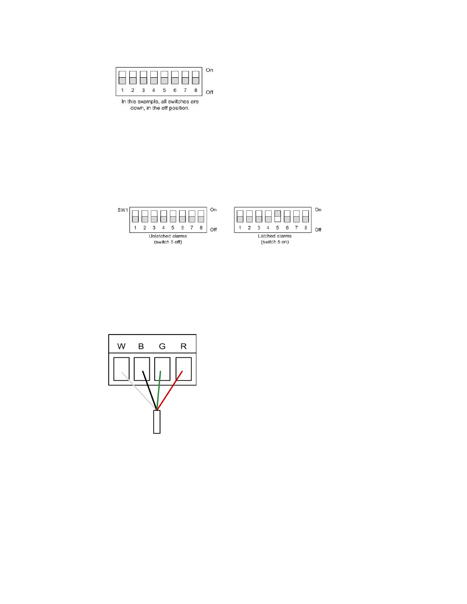
Figure 2.7
DIP Switch 5, SW1 - Latched or Unlatched Alarms
2.4.2 TB2: Leader Cable
1
A 15-foot (4.57m) section of non-sensing leader cable is supplied with each SeaHawk 10K.
The leader cable connects sensing cable to the SeaHawk 10K, since sensing cable cannot
connect directly to the unit. Insert its four stripped wires into the appropriate slots in TB2 –
from left to right: white, black, green, and red.
Figure 2.8
Cable Connection TB2
Note
If the terminal connector is removed from the end of the cable, make sure the wires are in
this same order, W - B - G - R, when the connector is reapplied.